I found this 3CX3000F7 RF Deck from a 13.56 mHz Eratron Model 80030 Plasma Generator. I was originally planning an easy conversion to 20 meters, but abandoned the idea since I am a night guy and 40 is an excellent band at night. I operated for years on 40 with this amp and it worked flawlessly. In 2015 I converted another amp from an 80 meter monobander to a tribander 160/80/40. The triband amp worked so well that this 40 meter amp sat on the side gathering dust.
40 METER CONVERSION
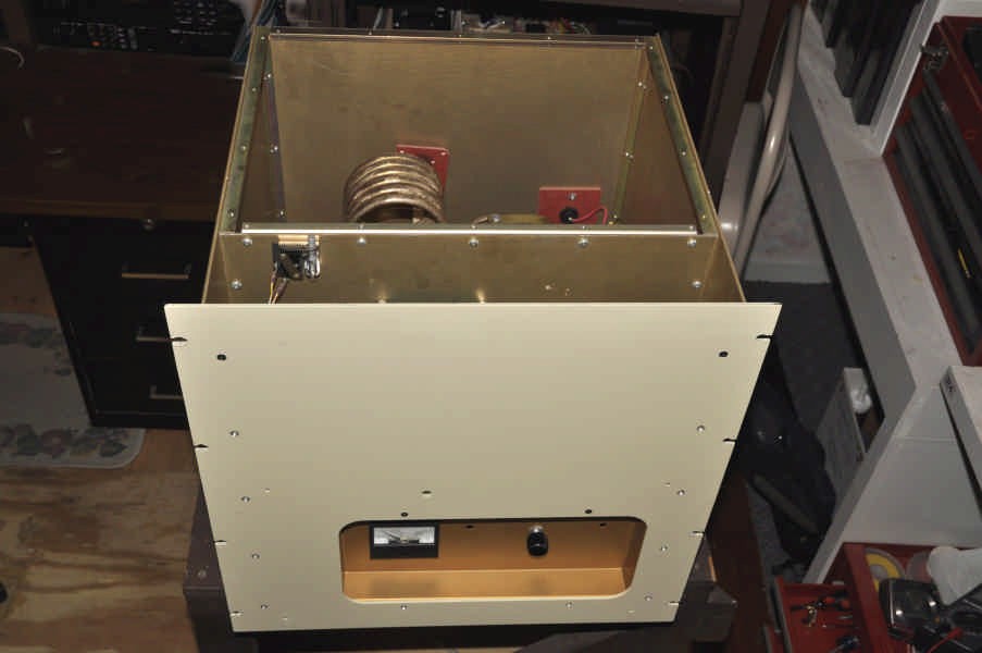
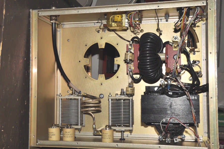
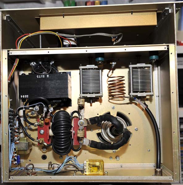
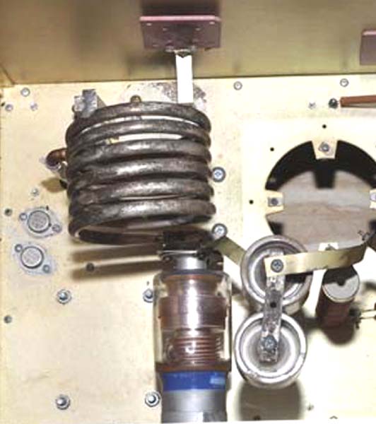
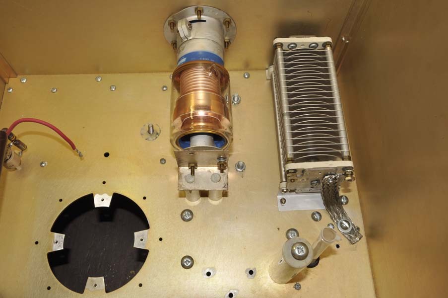
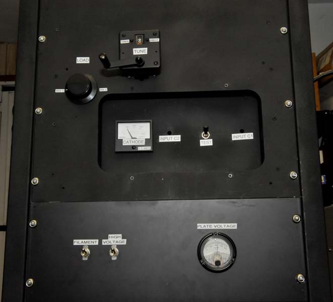
ORIGINAL UNMODIFIED 13.56 MHZ RF DECK:
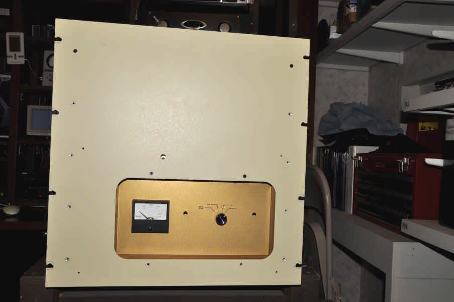

Front view
Front-top view
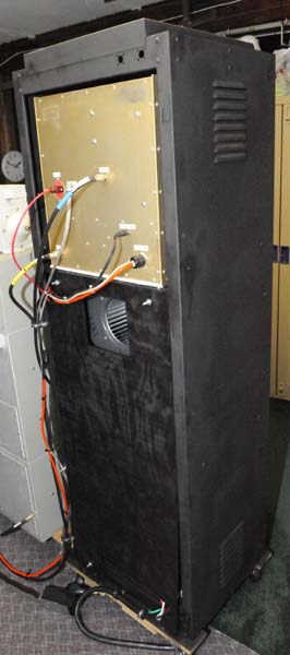
Top view
Bottom view
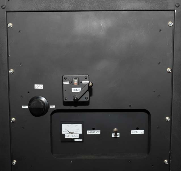
COMPLETED 40 METER RF DECK:


Front view
Top view
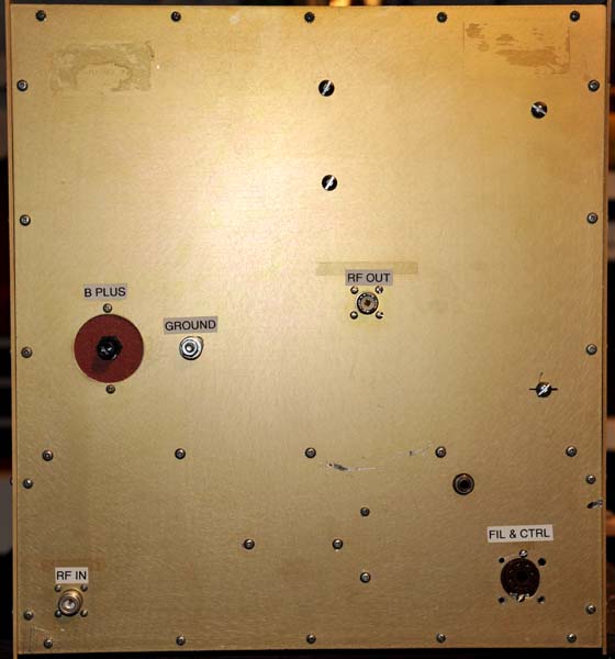
Bottom view Back View
RF DECK SCHEMATICS:
Original Cathode Original Plate Completed
Cathode Completed Plate
(see mods below)
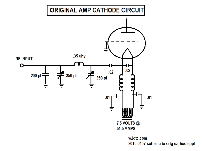
CATHODE CIRCUIT
CONVERSION:
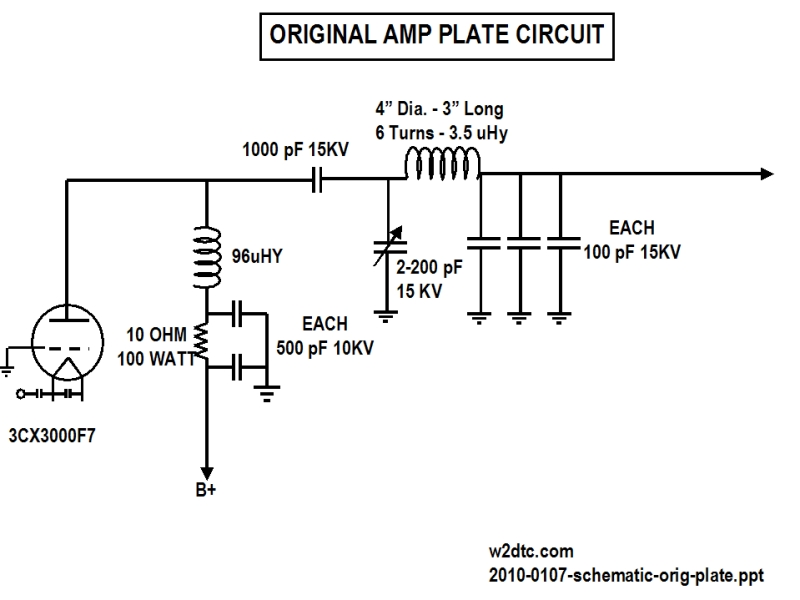
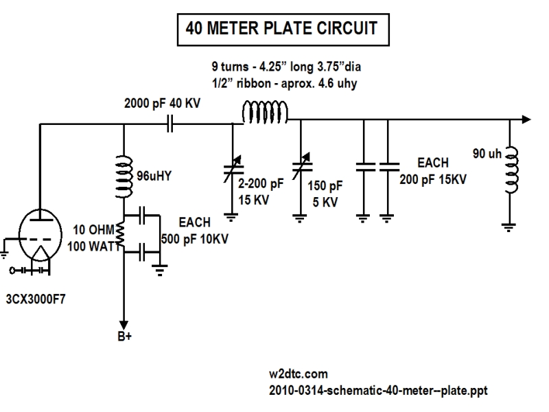
PLATE CIRCUIT
CONVERSION:
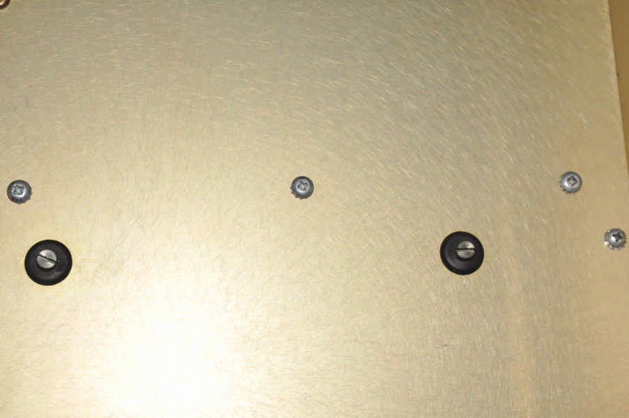
Original 13 mHz pi-network cathode circuit: The PI-network capacitors had very short shafts with slotted ends, that
extended only through the RF compartment; however, there are two holes in the
front panel to allow for screwdriver adjustments of these capacitors.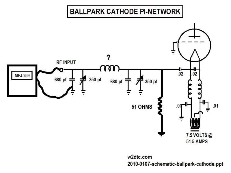

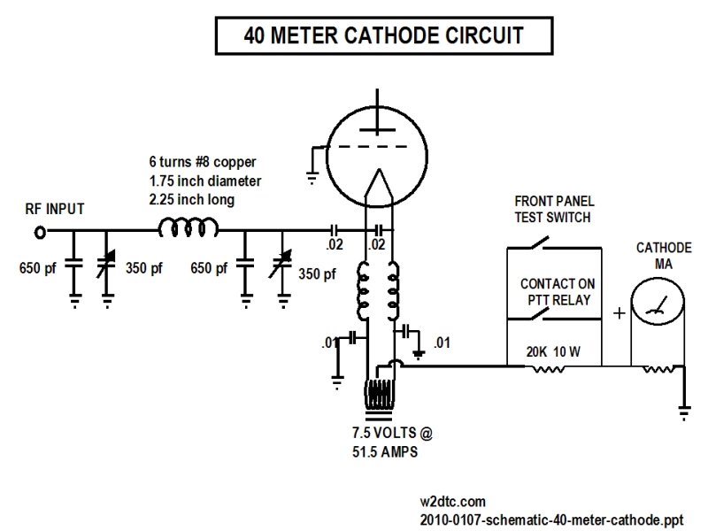
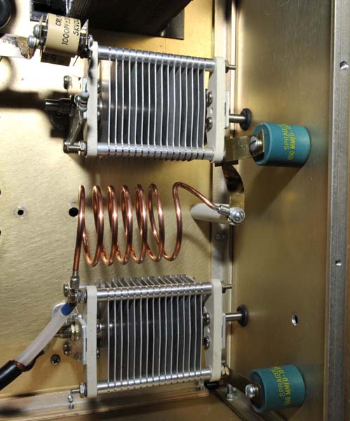
Completed 40 meter pi-network cathode circuit:
Removed the original 3 turn coil and replaced the original doorknob caps with 650 pfd units. Wound a 9 turn
coil of #8 bare copper around a flashlight. Hooked
up the MFJ-259 and the 51 ohm loading resistor and by trial and error, trimmed
down the coil until I found 6 turns would be perfect. ( 6 turns, 1.75"
diameter, 2.25" long) Low Q, flat from 6.8 to
7.5 mHz without retuning.
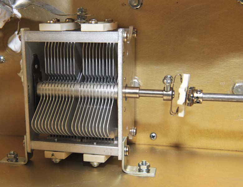
Original 13 mHz pi-network plate circuit:
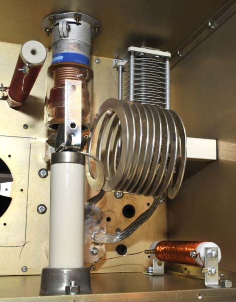
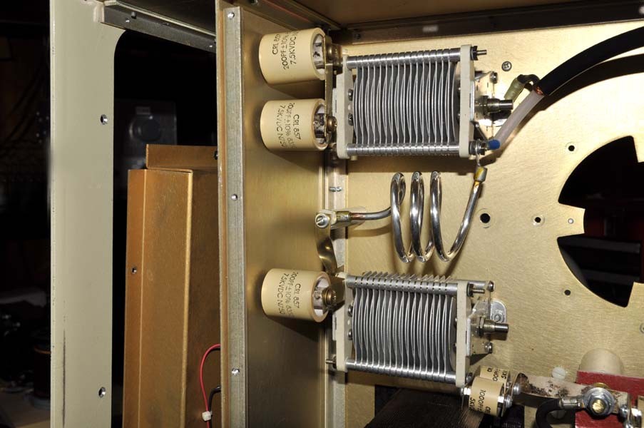
Completed 40 meter pi-network plate circuit: The original
pi-network output caps had fixed values to feed a
fixed load of 50 ohms. To accommodate loading into other than 50 ohms, I
added a 150 pfd breadslicer. (*** see modifications below as this was changed***). The original 100 pfd units were replaced with
200 pfd units. The resulting coil was 4.25" long, 3.75" in diameter wound with
1/2 in wide silver plated ribbon (aprox 4.6 uhy). Also added was a
90 microhenry protection choke.
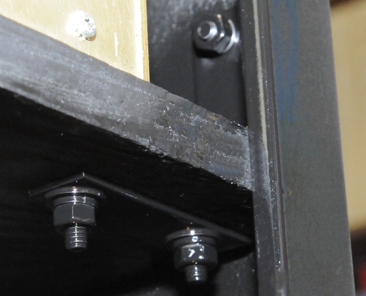
INSTALLED TURNS COUNTER FOR THE VACUUM
VARIABLE:
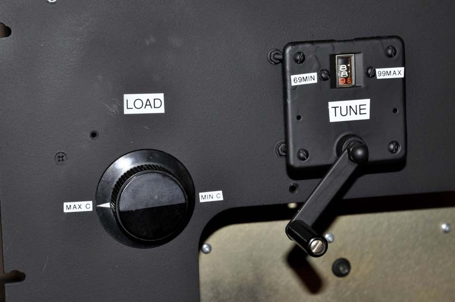

There was no room inside the cabinet, so the final amp pi-network turns-counter
was externally installed. It's ugly,
but it has a very solid connection to the vacuum variable.
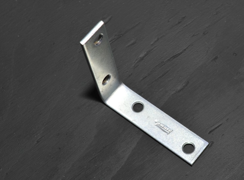
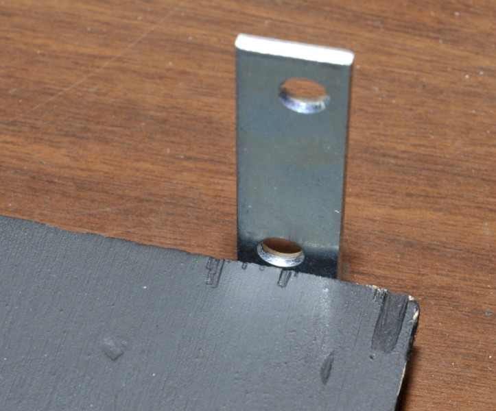
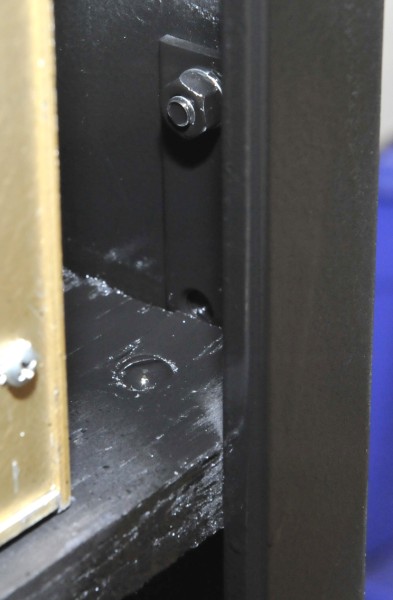

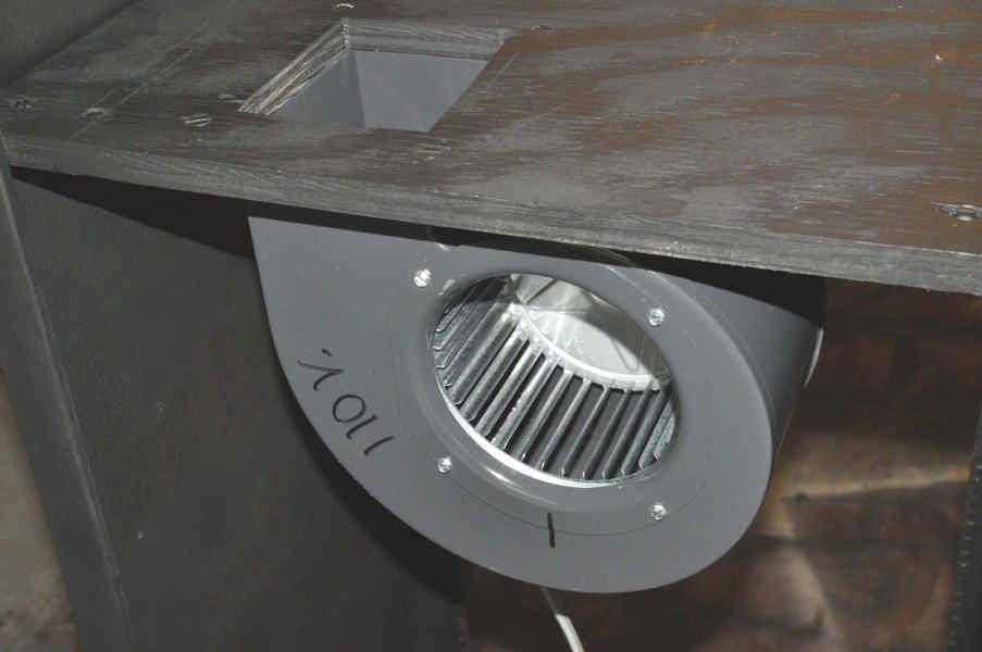
Installed and
spray painted (Rust-oleum flat black) 3/4 inch plywood shelf inside a 6 foot relay rack
using four 3" x 3" angle brackets. Cut a rectangular hole in
the plywood shelf and added the Dayton 4C870 blower motor: 1/10 HP, 1570 RPM. Fan is 6" in
diameter and 4" wide. RF Deck will be slid over hole in plywood, as
the hole was cut to line up with the tube.
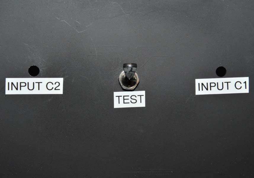
CONSTRUCTED 2 AMP PLATE CURRENT METER SHUNT:
BUILT HIGH VOLTAGE
POWER SUPPLY:
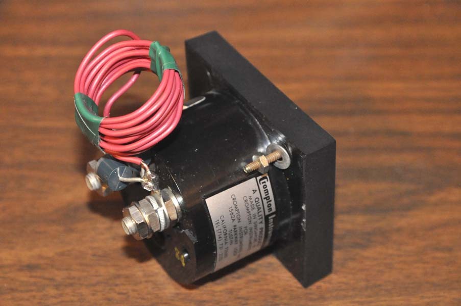
BUILD ANTENNA SWITCHING RELAY:
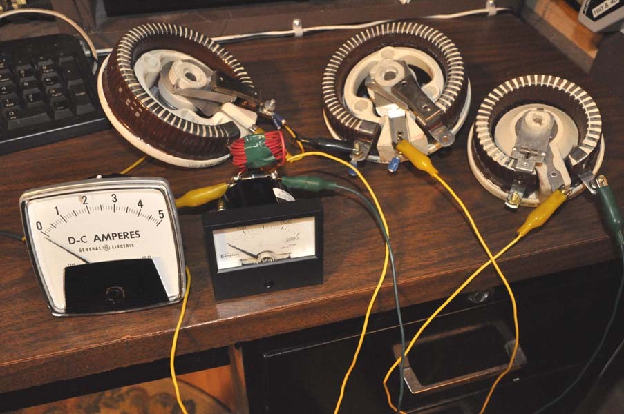
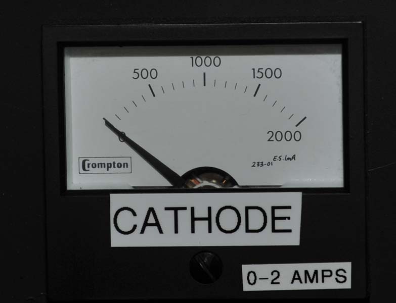
The
process involved putting the test meter in series with a known "standard" 2 amp
DC meter in series with a power source that could be varied. By trial and
error, a certain length of shunt wire will make the test meter read the same as
the standard meter. I found that a 3 foot length of #20 hookup wire did
the trick. I also added back to back diodes for meter
protection.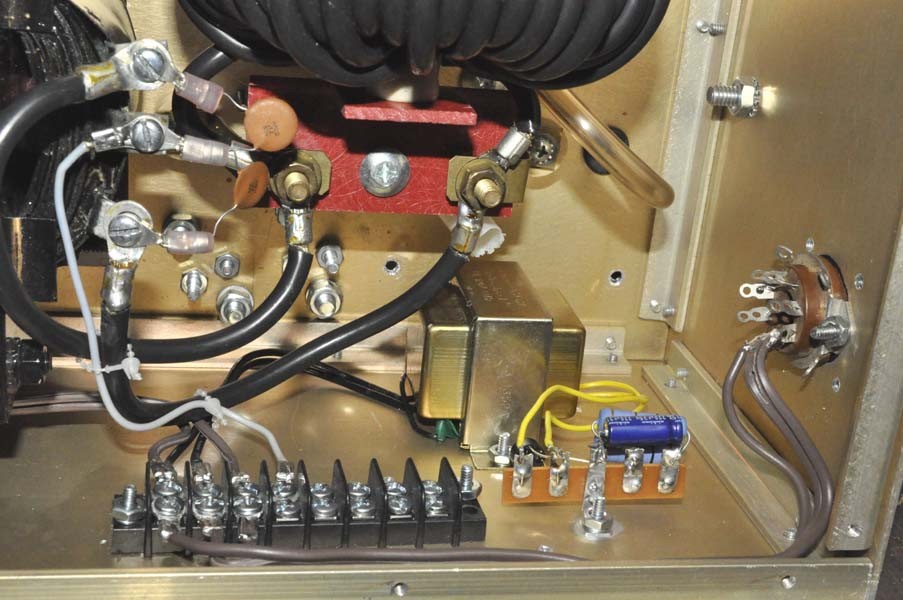
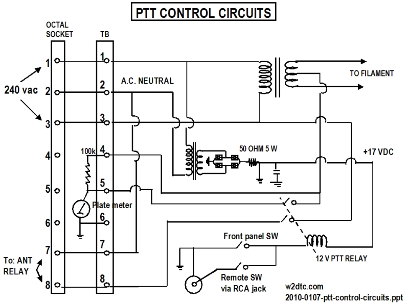
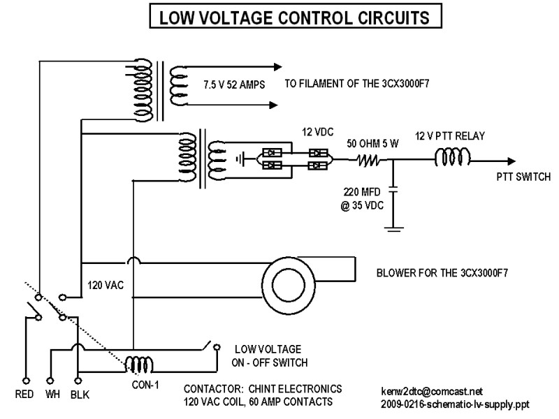
Using a series resistor in the DC path, the power supply provides about 17 VDC to turn on
the 12 VDC relay and then drops to 8.5VDC to hold it on. I expect the push-to-talk wire to be quite long from the shack to the garage.![]()
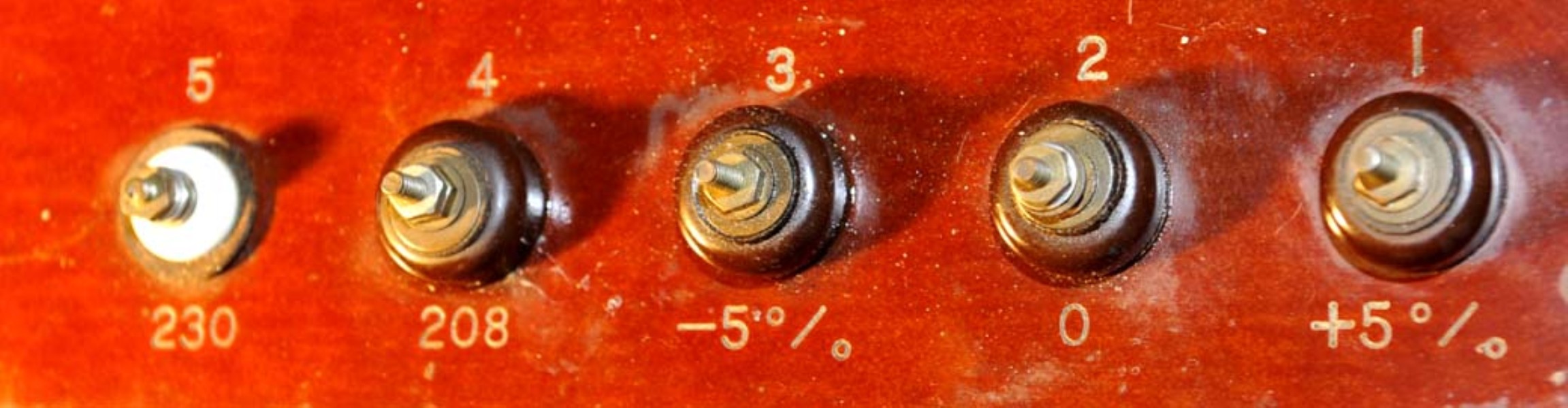
Expecting a 120VAC transformer, I was surprised to find
it was actually built for 220 VAC.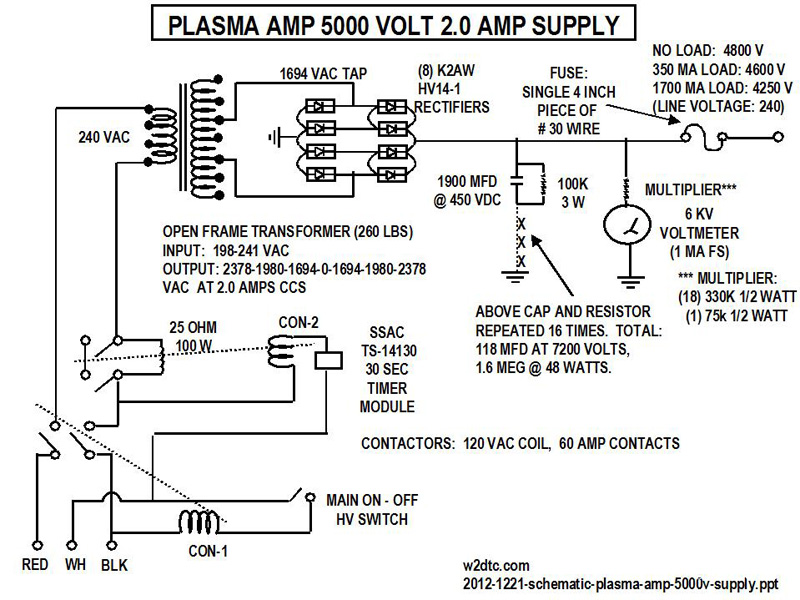

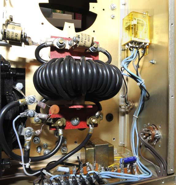
5000 volt supply Filament
and blower control
![]()

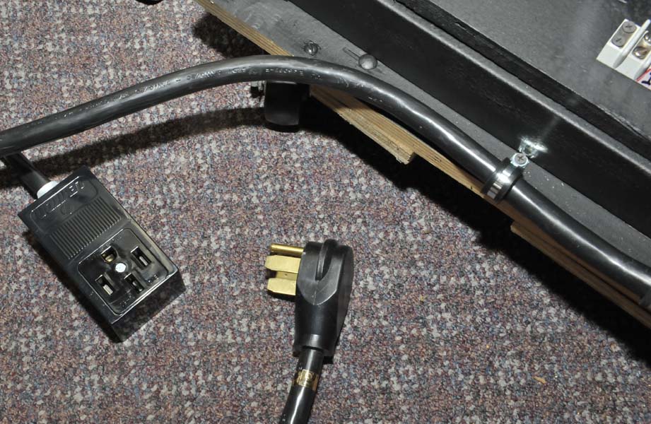
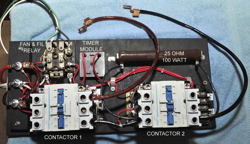
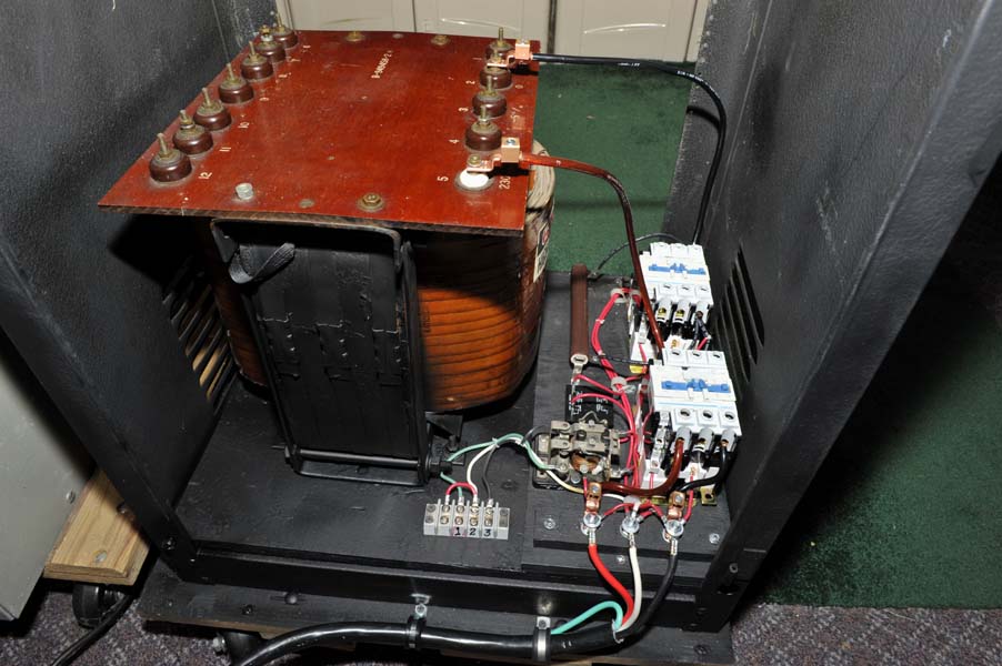
Installed transformer primary control module: Built the modular control unit on a 7.5" X 17" painted 3/4 inch
plywood board. Has 30 second delay step-start via a 25 ohm resistor and a
shorting contactor. Connected the control module to the AC power subpanel
via a 50 amp dryer plug and socket.


Installed (8) K2AW rectifiers on
a 5" x 8" x 1.25" aluminum heat sink and wired them in parallel.
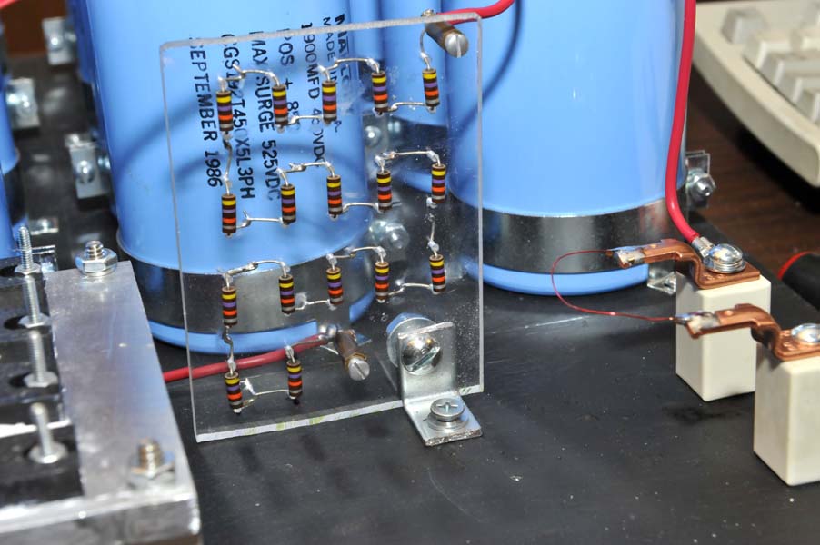
Installed (16) 1900 MFD @450 VDC computer grade caps on a painted 3/4 inch plywood and wired
them with 100K equalizing resistors. Total value is 118 mfd @ 7200 VDC. (note:
1.6 meg makes a poor bleeder; however, the 450 ma amplifier idling current
stabilizes the supply nicely and when I turn off the high voltage primary and
key the amp without drive, the tube conducts and the high voltage decays in
about 4 seconds). 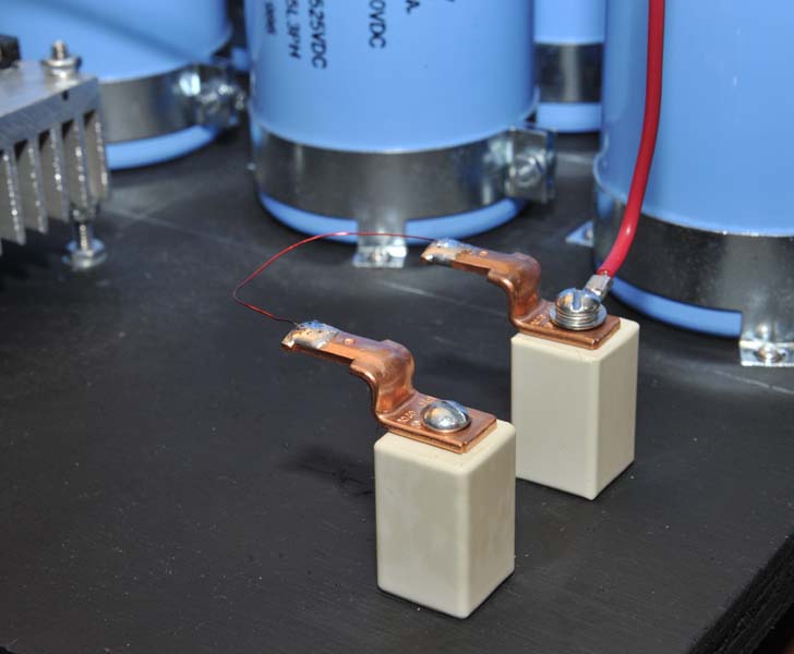
Installed a high voltage fuse
out of a 3 inch piece of
#30 magnet wire on standoff insulators. Installed a plate meter multiplier
via 17 resistors on Plexiglas.
Completed power supply: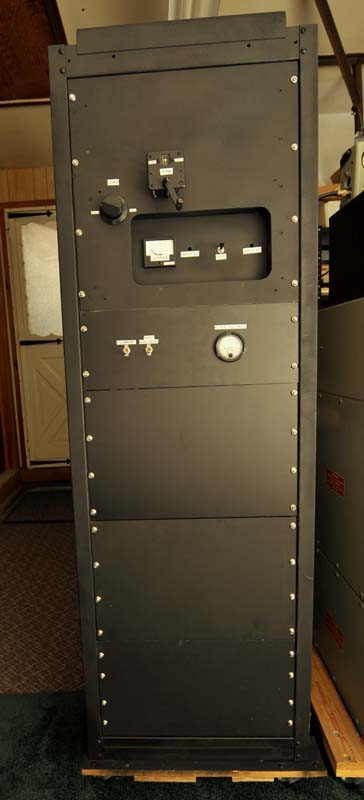
Completed amplifier.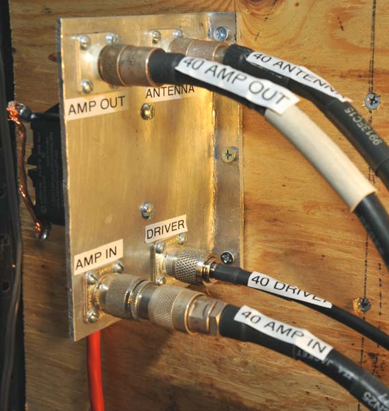
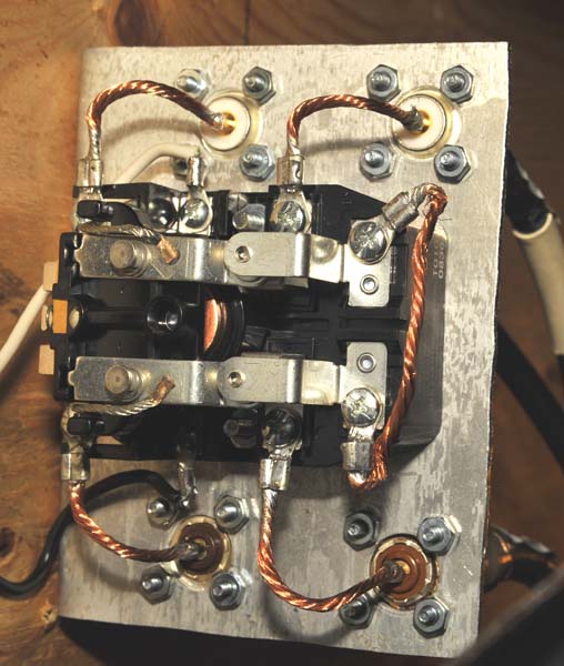
Installed a 25 amp DPDT relay on a thick piece of aluminum to which was
installed 4 coax connectors.
1. The power supply came right up with no problems and the DC voltage came out as
calculated.
The no-load high voltage was 4900 (note: 1.6 megohm bleeder). The high voltage dropped to 4700
under a 450 ma load, when
the amp was turned on with no drive. At a 1 amp load, the high voltage was 4600.
2. The first time I turned on the RF Deck, I applied 20 watts input and the pi-network tuned correctly
and output was developed. I increased power to 100 watts and got
approximately 2000 watts out. I was very pleased that the power supply and amp
came right up without smoke, fire or tripped circuit breakers !
3. The amplifier puts out 20 times the input, thus a 18 watt carrier input yields 360 watts output and a 300 watt input yields 6000 watts. (On the amps I have built without a tuned input, the amplification factor was only 14).
4. The input pi-network worked fine and the driver could be tuned to 1:1 SWR.
MODIFICATIONS:
1. While tuning up under AM modulation conditions, monitoring with a scope, I
found that I couldn't quite load the amp to full output into loads different
than 50 ohms because the 150 pfd pi-network
cap was not enough capacitance. I should have put in a large variable right from the start.
I now have a 27-1000 pfd variable and loading is perfect into dummy load or
antenna.

![]()
![]()