SX-62 General Specifications:
Band 1: 550 - 1620 KHZ AM/CW IF = 455 KHZ
Band 2: 1.62 - 4.9 MHZ AM/CW IF = 455 KHZ
Band 3: 4.9 - 15 MHZ AM/CW IF = 455 KHZ
Band 4: 15 - 32 MHZ AM/FM/CW IF = 10.7 MHZ
Band 5: 54 - 109 MHZ AM/FM/CW IF = 10.7 MHZ
Audio flat from 50-15,000 cycles, 10 watt push pull output. (from Ad in 1951 ARRL handbook).

I purchased the SX-62 at an Antique Radio Swapmeet in Kutztown, Pa. Checking it out at home, a couple of the bands were working and the audio was quite good. The crystal calibrator and CW oscillator did not work and band 4 was not working. The receiver is rather large physically as compared to the white 12" ruler shown in photo 1. My revitalization project involved getting the receiver to perform as it did when it was new, no effort was made to make it better cosmetically.
Steps taken in the revitalization:
1. TUBES: All tubes checked good on the emission tester except I had no test for the loctal type 7F8 local mixer/oscillator. I went on ebay and found a couple of new ones. When I tried the new ones, the signals on the upper bands increased noticably. I threw out the original tube and stored away the new spare.
2. PAPER CAP REPLACEMENT: Using a scope and voltmeter I replaced the caps that were leaky; however, a day after finishing that project another cap failed so I 'bit the bullet' and replaced ALL the paper caps with orange drops. I didn't count but there must have been at least 20 caps replaced.
There were a couple of caps in the RF amp section that looked impossible to change, but I was determined. With my small cutters, I snipped the upper end wire on the cap, which was barely accessible, and rotated the paper cap body many, many times with diagnals until the metal finally broke at the lower end. Fortunately the wire broke close to the cap, leaving a decent length wire lead that allowed me to solder in the new cap. I modified one of my soldering guns by replacing the normal tip with a rather long piece of #12 copper wire. With the new tip I was able to bend the tip in any configuration to reach the hard to get at component.
3. BFO OSCILLATOR FIX: After checking the oscillator tube, the voltages and the resistances and finding nothing out of the ordinary, I removed the shielded can. Checking internal resistances proved nothing was wrong here either. As I was putting the shield back on the assembly I noticed a brown paper tape up one side of the shield and it looked like factory tape. I also noticed that there were sharp points on the internal connections and it looked like they may have touched the can or pierced the paper tape so I put two strips of plastic tape down each side of the coil/capacitor assembly and reinstalled the shield. That was it, the BFO was now oscillating.
4. CRYSTAL CALIBRATOR: The oscillator was actually working but the output was very weak and after the the IF and RF alignment was completed the signal was usable; however, the gimmic capacitor was replaced with a 10 mmfd silver mica to increase the output.
5. BAND 4 FIX. Apparently the previous owner was starting to replace the paper caps and removed one of the old ones when he stopped the project. I discovered the missing cap and when the new orange drop was put in, band 4 started working.
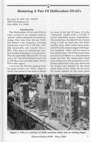
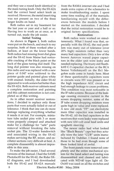
6. OUT OF TOLERANCE RESISTORS: Nearing the end of my revitalization project I received my May 2004 issue of Electric Radio and Mr. Larry Will W3LW had an article on the subject of "RESTORING A PAIR OF HALLICRAFTER SX-62's". I couldn't believe the timeliness of his article. Larry suggested that some of the resistors were out of tolerance and upon checking, I found out he was right so I replaced a few of them in the process. A couple of the 220K resistors in the audio screens were at 357K !
Mr. Will was kind enough to allow me to put his article on this webpage.
Larry said it's his enjoyment to share information with other radio enthusiasts
and I applaud that.. (Note: after left clicking your mouse to obtain the
larger image, left click your mouse again, over the words, and the article
should be very readable)


7. ANTENNA CONNECTION. Someone had drilled a hole in the back of the receiver for some reason and never finished the project, so I drilled it out a little and installed an SO-238 coax connector for the new antenna connection.
8. IF AND RF ALIGNMENT. Prior to alignment I sprayed DeoxIT on all wafers of the band switch while moving the switch back and forth many times. I also sprayed DeoxIT on all pots and the variable caps. After 5 minutes I repeated the spaying of DeoxIT. After another 5 minutes I sprayed WD-40 on the variable cap contacts. Even though a few minutes would have been sufficient I waited two hours before turning on the power. After the IF and RF alignment there was a remarkable improvement in the receiver performance. During the RF alignment, the very old dial cord broke so it had to be replaced. I'm not good at dial cord work and this took me well over an hour to string the new one.
I'm very happy with this old circa 1949-1953 receiver. Coverage from 0.55 MHz to 109 MHZ makes it a great general purpose receiver. This receiver should not be compared to a communications receiver because the single dial has insufficient frequency accuracy and while listening to SSB I have to re-tweak the dial every five minutes to bring "Donald Duck" back to a normal voice. In a pinch, I could use it on AM when the band is not crowded and while the receiver IF is quite wide, the crystal filter allows me to tune the 75 meter AM frequencies and separate stations that are 10 KHZ apart. All said and done, it sure is a pleasure listening to the great audio from this vintage Hallicrafters receiver.
IN FEBRUARY 2015, I received an email with some very worthwhile advice on restoring this receiver from Tom, W0EAJ who gave me permission to post his comments:
To clean the knobs... immerse them in a solution of dishwater.. let soak a few minutes, then scrub with an old toothbrush... (be sure to screw the allen-screws in, so they're using ALL the treads of the hole - you don't lose 'em in the water, that way).. after that, blow excess water out...let air dry, then spray some regular PLEDGE into your hands.... roll each knob around in our hands, to shine 'em up, as the Pledge will make them look new (do NOT spray it ONTO the knob, directly!)
http://daileyservices.com/vintage_radios/index.htm
303 / 455-0889 or radio@daileyservices.com
Tom Dailey also found another site for repair of the SX-62 including information on how to string a dial without removing the front panel:
http://pcbunn.cithep.caltech.edu/jjb/Hallicrafters/SX62/sx62.htm
Thanks Tom for sharing your information and experiences !