The 3CX3000F7 power grid triode with its 4000 watt plate dissipation loafs along at legal limit Amplitude Modulation, plus It only needs one D.C. power supply. The rugged 3CX3000F7 has a grid dissipation of 225 watts vs the popular 8877 which only dissipates 25 watts. The 3CX3000F7 (up to 30 mHz) is exactly the same electrically as the 3CX3000A7 (up to 110 mHz). The 3CX3000A7 requires a tube socket whereas the F7 is bolted to the chassis. The cabinet, PI-L tank and right angle drives were leftovers from a partially completed commercial Gates transmitter. With the major mechanical parts in place, the 80, 40 and 20 meter design was easy to build. In 2007 I added the 160 meter band, which is described near the end of this webpage. (Schematics are also included).
click on any photo to ENLARGE
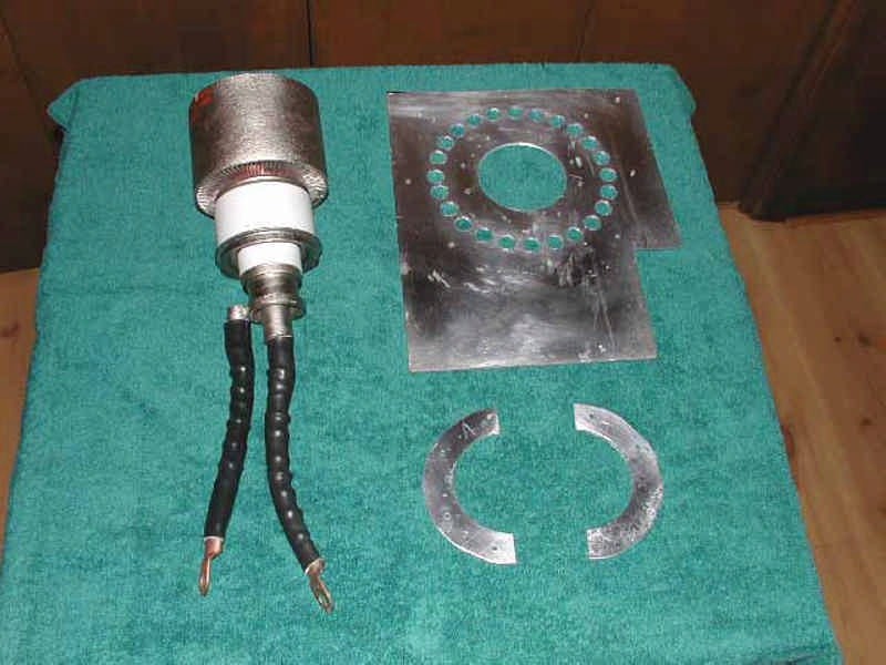

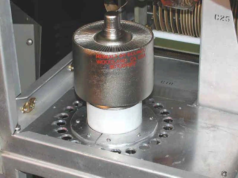

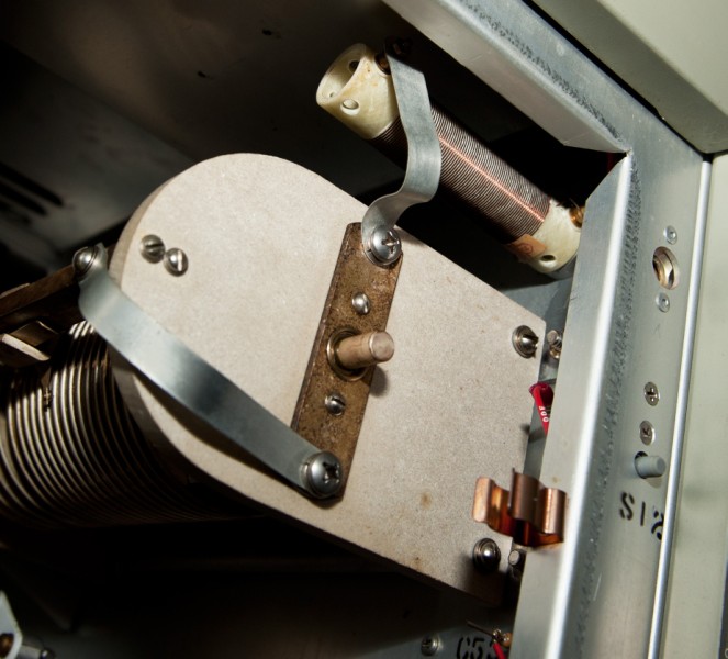
The original Gates 4CX3000A socket and wiring was removed and a homebrew heavy aluminum template for the 3CX3000F7
was mounted on
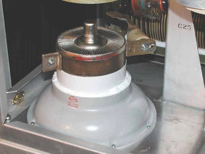
the Gates chassis. Installed the 3CX3000F7 by setting it's grid ring on the top of the
homebrew template and holding the grid ring down with two heavy homebrew aluminum half-circle mounting strips. I had an Eimac SK-1406 tube chimney for a physically larger 4CX3000 so I made up the space difference by inserting a ring of teflon between the tube and the chimney and "glued" it in with GE Silicon Kitchen and Bath caulk.
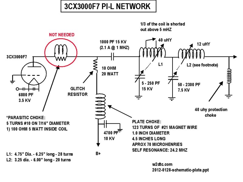
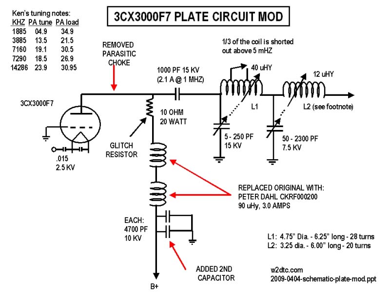
Added a homebrew plate choke, glitch resistor and homebrew parasitic choke (plate circuit schematic at bottom of this webpage with wire size and turns count). Full power tests on the 3CX3000F7 were conducted on the popular AM frequencies of: 3885 kHz, 7290 kHz and 14286 kHz with no signs of instability.
(NOTE: Internet research revealed that no parasitic choke was required with this grounded
grid triode and I removed it when I made my 160 meter modifications). See 160
METER MODIFICATIONS below.
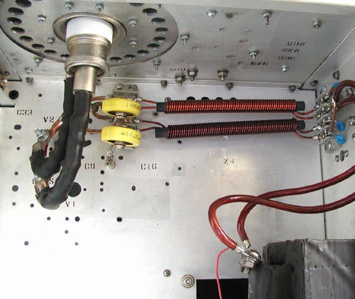
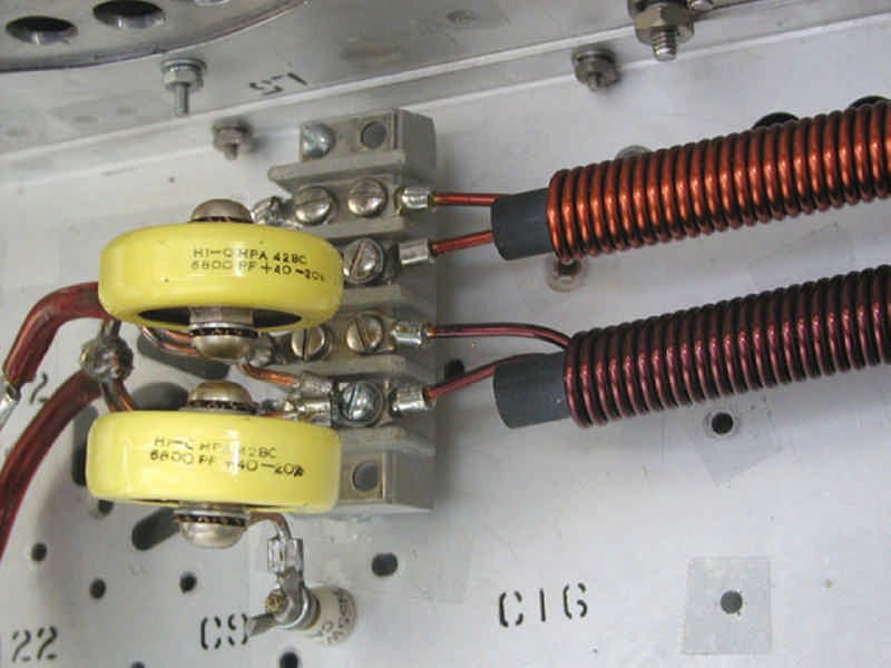


Installed the 3CX3000F7 filament transformer, two 30 amp filament chokes in parallel, the RF drive coupling caps and
installed eleven 6 amp diodes between the center tap of the filament transformer and ground to set the bias at -7.7 volts for a no drive idling plate current of 325 mills. The original 1000pf coupling caps were replaced by 6800pf (yellow ones) for a little better match to the cathode as noted by less reflected power. Since there is still some reflected power with the 6800pf capacitors it suggests that an even greater value would be better.
(NOTE: 1. Internet research revealed that the bias diodes
were unnecessary and were removed. 2.
For 160 meters the two filament chokes were replaced with a higher inductance
choke). See 160 METER MODIFICATIONS below.
ANTENNA PROTECTION CHOKE:
If the plate coupling capacitor should short out, this 40 uHy choke from the ouput PI-L inductor to ground (same as being across the output coax connector) will short the B+ and cause the high voltage fuse to blow.
click on any photo to ENLARGE

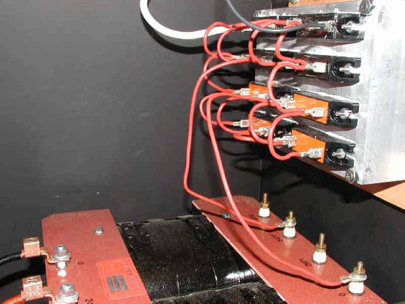
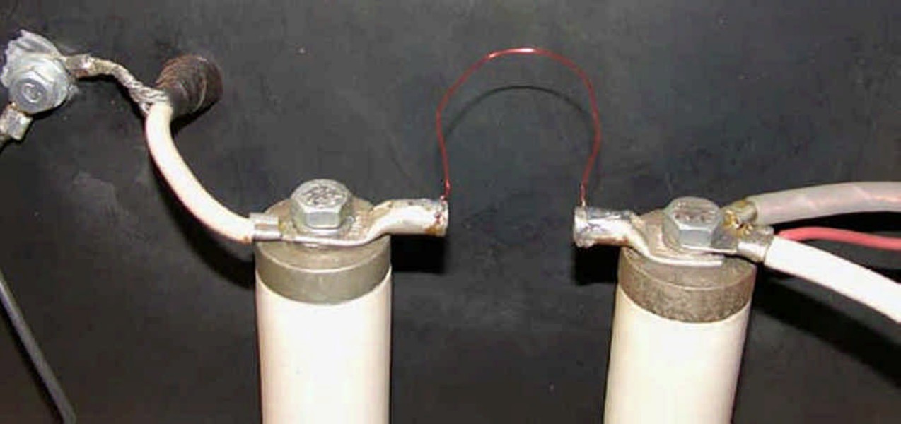
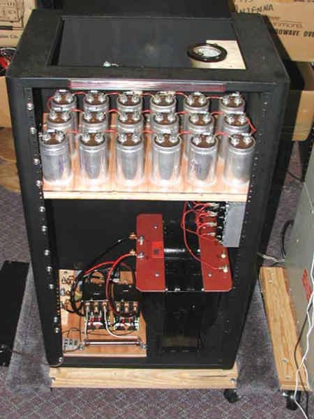
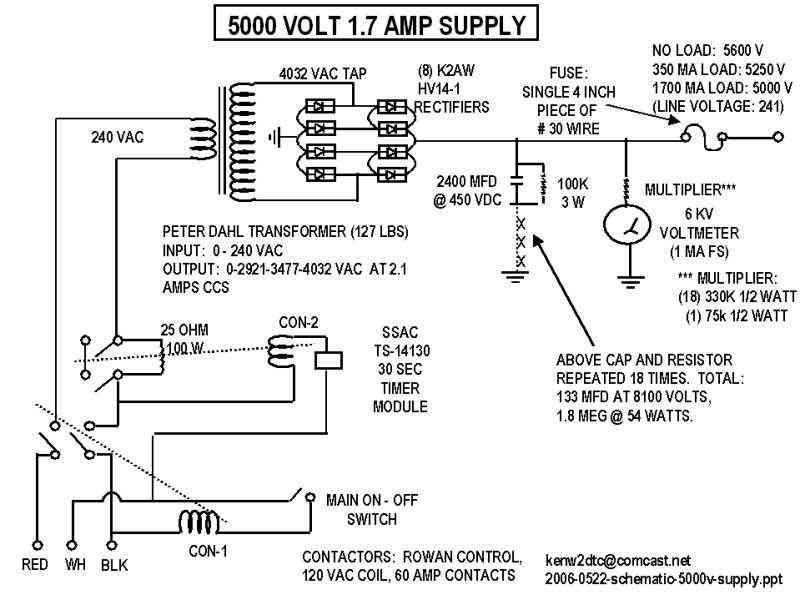
Built a full wave bridge, capacitive input, Peter Dahl transformer based 5000 Volt power supply into a standard 3 foot Bud cabinet (Schematic at bottom of webpage). A soft-start delay was built using a 30 second solid state cube (ABB SSAC Solid State Timer part number TS14130) in series with a 60 amp contactor that shorts out a large wire-wound start-up resistor. For diodes I paralled two sets of 14KV K2AW Silicon Alley rectifier diodes and mounted them on a 5" x 7" x 2" heat sink. The high voltage fuse between the two standoff insulators was made from a single four inch piece of #21 magnet wire. If there is a high voltage short in the 3CX3000F7 compartment, the fuse material explodes and disappears (this feature was tested). High voltage wire between the power supply cabinet and the amplifier has a 30KV rating and is encapsulated in shielding stripped from LMR-400 coax cable, which is grounded at both the amp cabinet and the power supply cabinet. The power supply has a rating of 5000 Volts at 1.7 amps CCS with a 133 MFD 8100 volt bank of computer grade caps inside a Bud cabinet. The power supply cabinet and the 3CX3000F7 RF Deck cabinet are connected by Scotch 25 Electrical Grounding Braid which also connects to the common point station ground.
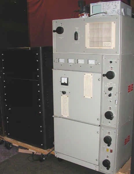
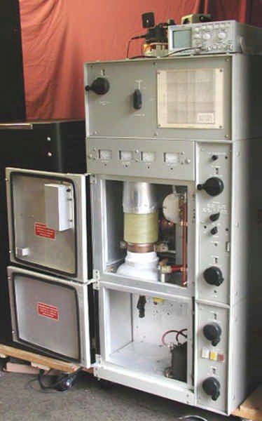
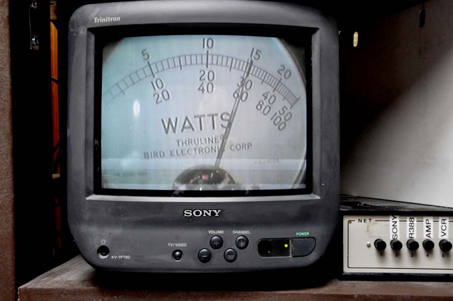
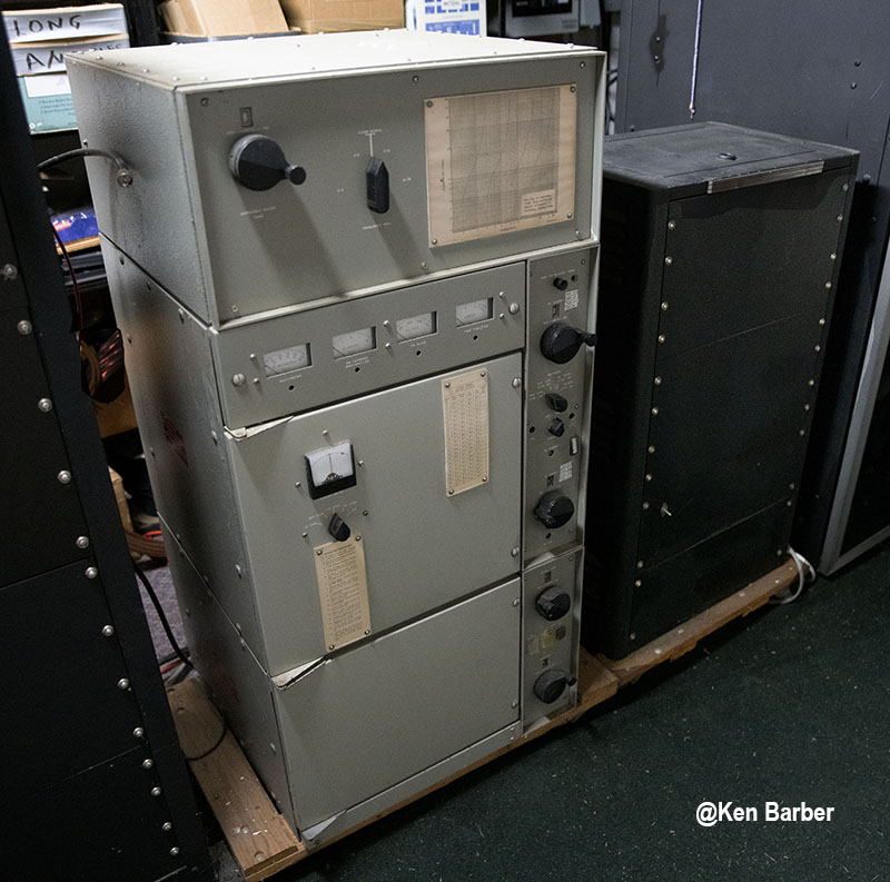
Outside view of both the 3CX3000f7 linear, the power supply and the remote viewing wattmeter. (The top section of the 3CX3000F7 amp cabinet has a switchable inductor and a vacuum variable for tuning out the 2nd harmonic; however, the 2nd harmonic is so far down that I keep it in the switched-out position). Even though I have an oscilloscope at the operating desk in the ham shack, I added an inexpensive oscilloscope and RF pickup loop in the garage to save me those back and forth trips while tuning up. The wattmeter reading camera has a 900 mHz transmitter. Video output from the remote 900 mHz receiver plugs into a video monitor in the ham shack.
POWER UP TESTS:
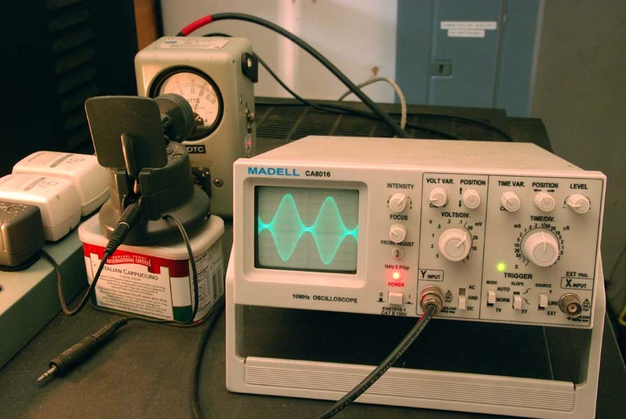
Tests were conducted at 3.885 mHz with the following setup (refer to block diagram below):
The AM driver transmitter was 100% modulated by a 1000 cycle audio tone. The input and output waveforms were sampled with RF pickup couplers and oscilloscopes. After the initial highest power test, with amplifier loading controls adjusted for linear operation, the 1 KW Navy dummy load (DA-75/U) was given a cooling off period, then the rest of the power output tests were completed.
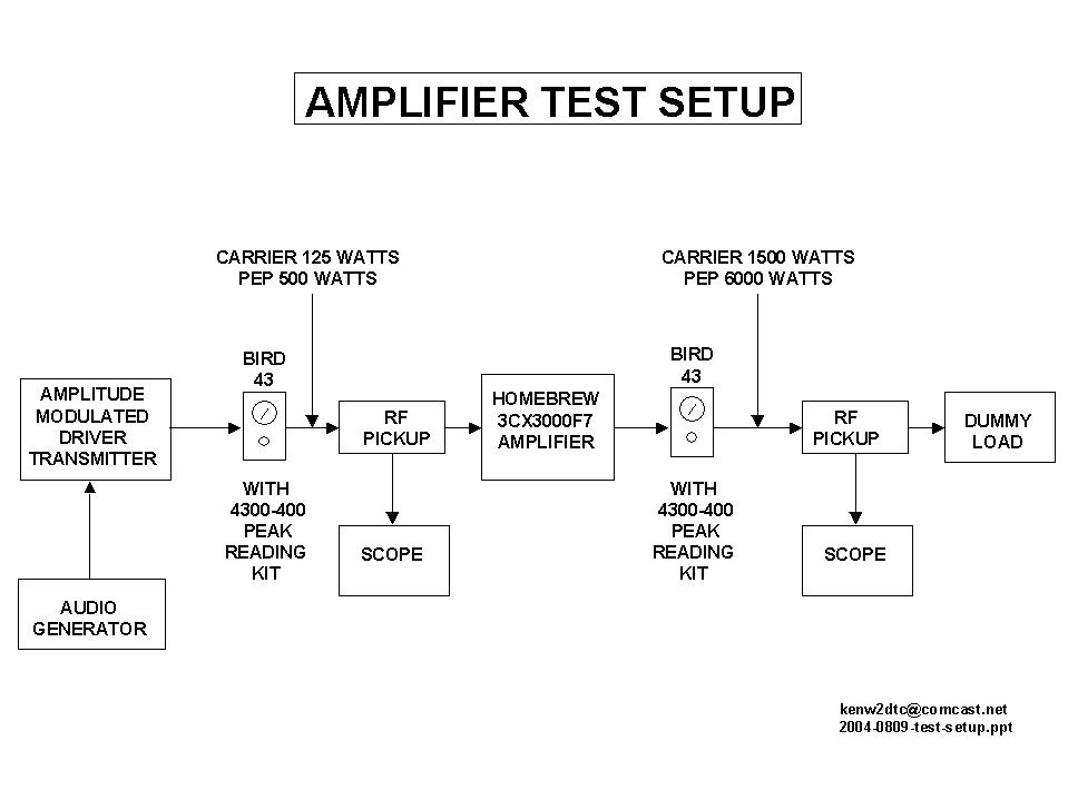 Block diagram of test setup prints
best in landscape orientation.
Block diagram of test setup prints
best in landscape orientation.
NOTE: When the final tank circuit was tuned for the highest RF carrier, using Bird wattmeter
readings, significantly more output power was obtained than the data shown
below; however, when modulation was applied, the oscilloscope showed distortion.
The final tank circuit was retuned for true linearity with an AM waveform on the scope
and the data (shown below) was recorded. The plate voltage
was 4500 VDC.
Input and output power in linear operation:
25 watts in---- 300 watts out
50 watts in-----600
watts out
100 watts in---1200 watts out
200 watts in---2400 watts out
300 watts in---3600 watts out
400 watts in---4800 watts out
500 watts in---6000 watts out
Since the output power is twelve times the input power, I set the AM driver transmitter for
31.25 watts of carrier (125 watts PEP) which yields a 375 watt carrier and a clean 1500 watts PEP. Another nice thing about the extra 3CX3000F7 tube plate dissipation is that
I don't have to retune the amp to move around the band, even when the antenna
feed presents a less than desired SWR reading.

A
B
C
A: Schematic of the 3CX3000F7 plate circuit (print in landscape orientation).
B: Schematic of the 3CX3000F7 cathode circuit (print in landscape orientation).
C: Schematic of the 5000 volt 1.7 amp plate supply (print in landscape orientation).
The 3CX3000F7 amplifier photographed and described above has been operating flawlessly for three years on 80 and 40 meters. Documentation on the original Gates amp indicated that it was a 2 to 30 mHz design. Being interested in 160 meters, I measured the PI-L with an MFJ 259 and discovered that the PI-L would
easily make 1885, which is a popular AM frequency, so I decided to make mods to this amp.
(In actual dummy load testing, the amp actually makes full power down to 1800).
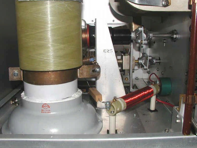
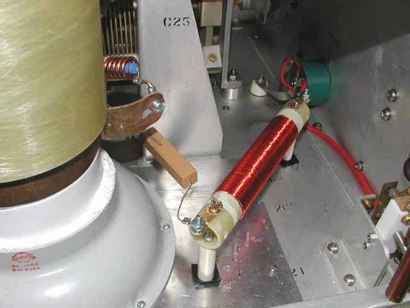
MOD #1, REMOVED PARASITIC CHOKE AND REPLACED PLATE CHOKE:

1
2
3
4
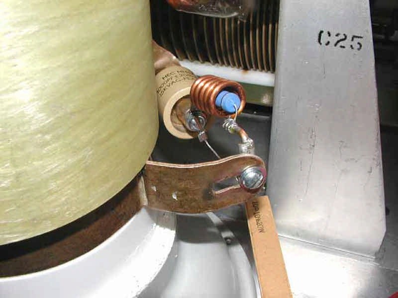
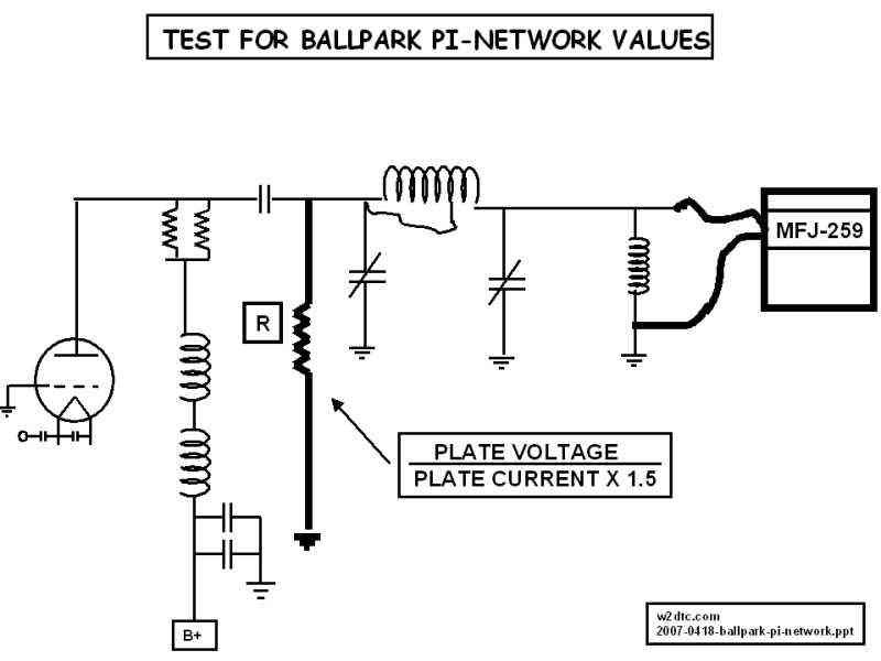
1: Test for PI-network range. (using clip leads, a carbon resistor was added for the test).
The idea is to preset C1 and C2 to calculated values and tap the coil until
resonance is
obtained on the MFJ.
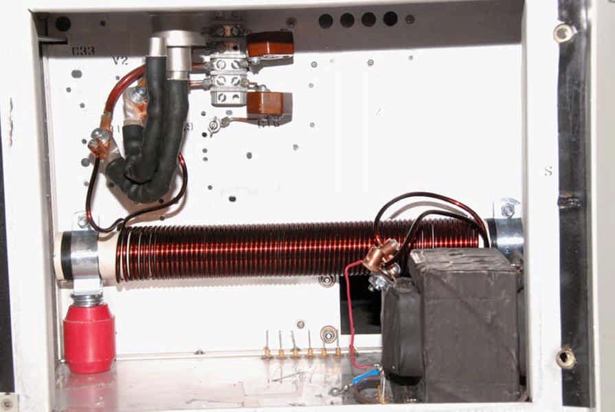
2: Removed the unnecessary parasitic choke and removed the old homebrew plate choke
and replaced it with two Peter Dahl 90 uHy plate chokes in series. (180 uHy total now
in the circuit).
CONSTRUCTION: 6.7 inches long, 5/8 inch diameter grooved Delrin
Rod, 123
turns of #24 magnet wire.
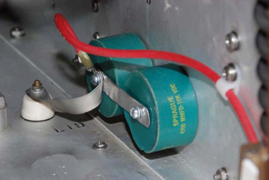
3: Added a 2nd plate choke bypass capacitor. (fat red wire shorts B+ to ground if the
cabinet door is accidently opened).
4: Schematic of the plate circuit mods.
MOD #2, REPLACED DUAL FILAMENT CHOKES AND REPLACED COUPLING CAPS:

1
2
3
4
1: Replaced the two B&W filament chokes with a single Peter Dahl 180 uHy 75 amp
filament choke.
Choke Construction: 16 inches long, 38 bifilar turns
(by count 76 wire
turns divided by 2) of #8
wire wound around 7 ferrite rods on a 1 1/2 inch diameter form.
(Not sure how many rods sets
needed for a length of
16 inches).
The choke weighs 6.5 pounds.
2: Silicone rubber end cap removed to reveal the seven 1/2 inch diameter ferrite
rods.
3: Replaced the 6800 pfd caps with .015 mfd @ 2.5KV mica caps.
4: Schematic of the cathode circuit mod. Notice the removal of the bias diodes which are
not needed. With diodes the idling current is around 235 mills with no diodes the idling
current is around 360 mills.
With these mods, the amp makes full power on 160 meters.
The Gates
conversion transmitter is large: 22" x 22" x 45 inches and weighs several
hundred pounds.
![]()
![]()