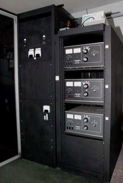
In 2005, this amp started as an 80 meter two holer, six years later it was converted to a one holer and in 2015 it was converted to a 160-80-40 meter tri-bander.


1
2
3
4
5
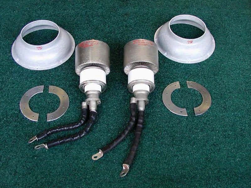
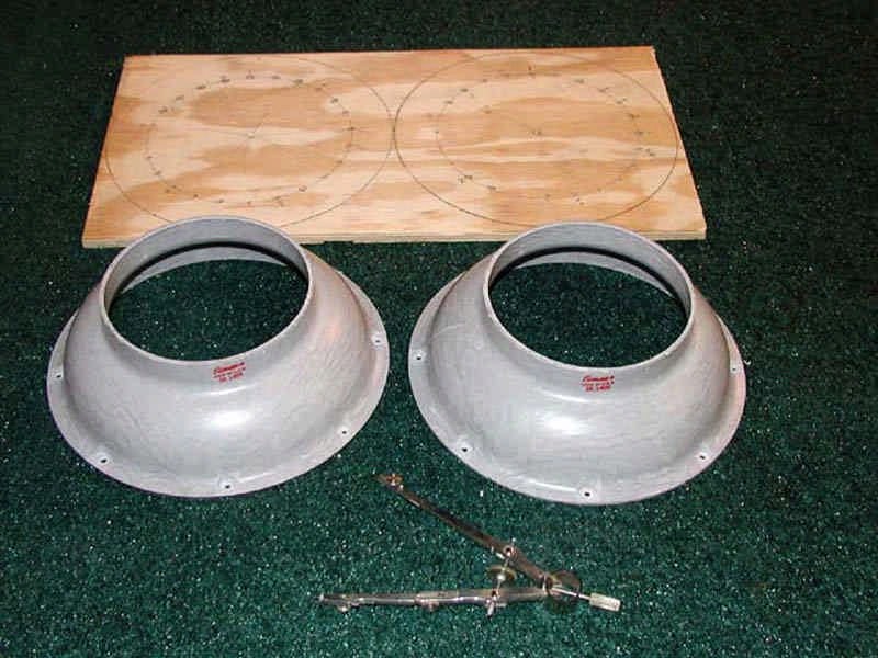
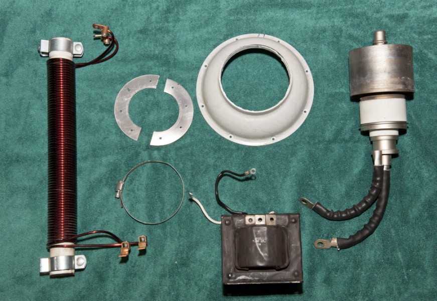
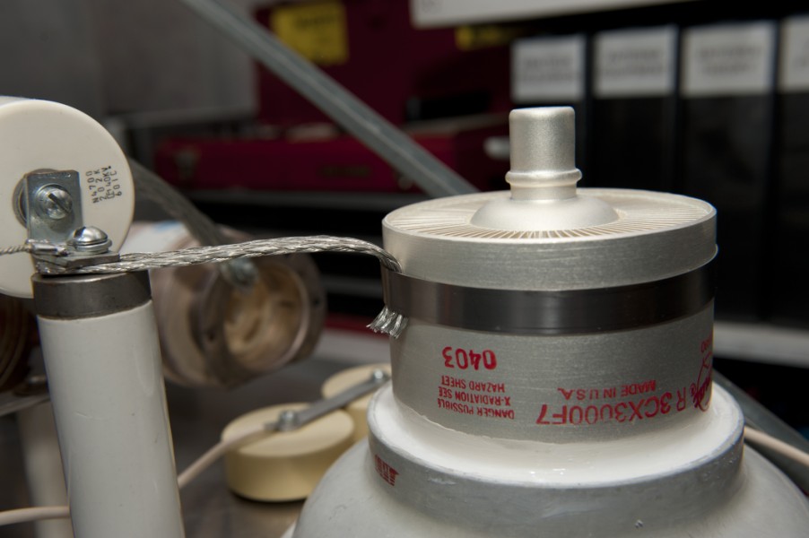
1: Oversized SK1406 chimneys, 3CX3000F7 tubes and 1/8" thick, 1" wide, half-circle
aluminum tube clamps.
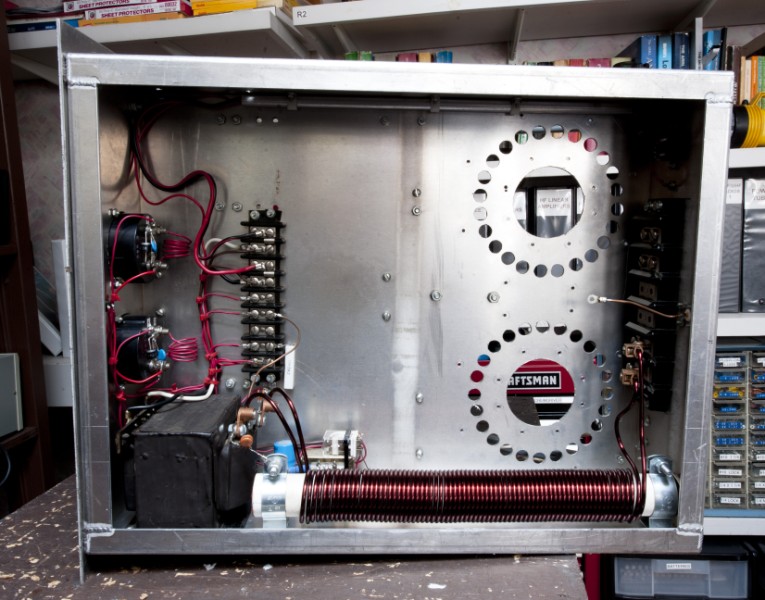
2: Created a 1/4 inch plywood "drill" template using the tube chimneys and a draftsman's
compass.
3: Three inch tube holes and 5/8 inch cooling holes drilled into 1/8" thick 22" x 17" x 6"
aluminum chassis.
4: The tube grid rigs are larger than 3 inch chassis holes; therefore, the tubes sit on
top of
grid rings and fastened down with 6-32 hardware.
5: The space difference between the oversized chimneys and the tubes was filled by
inserting a 2" x 13 9/16" strip of .060 inch thick teflon and "glueing" them in with GE
Silicon Kitchen and Bath caulk.


6
7
8
9
10
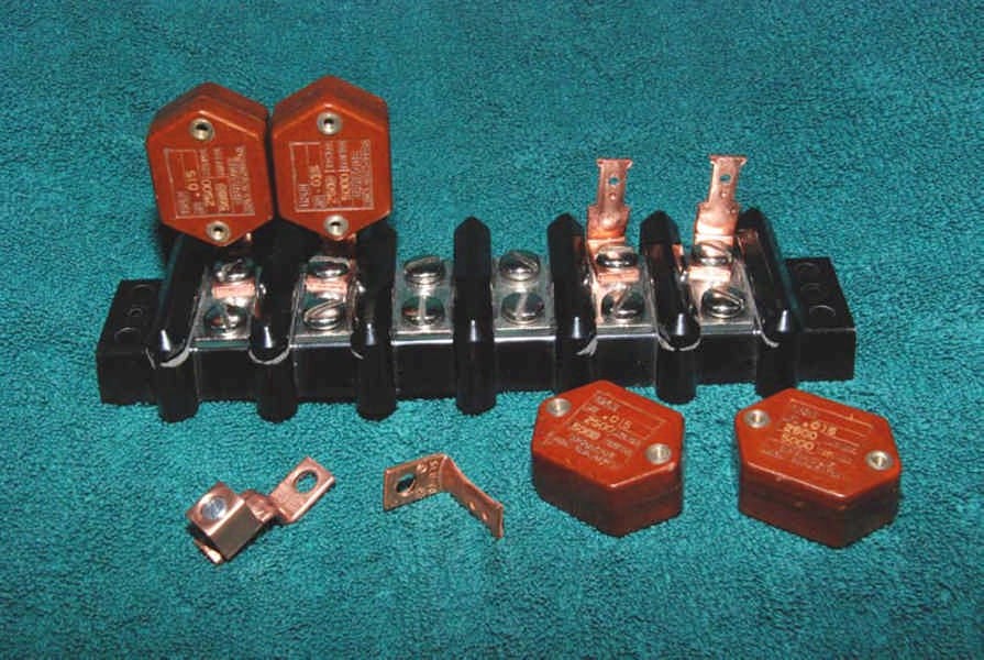
6: Method of mounting the .015 ufd, 2500 V transmitting capacitors to the 8 1/2
inch long
Bakelite terminal strip.
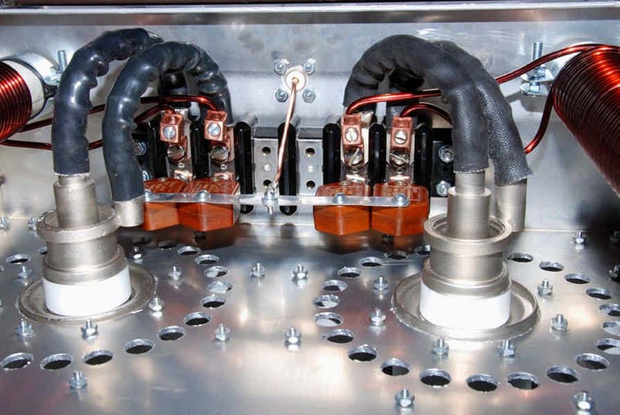
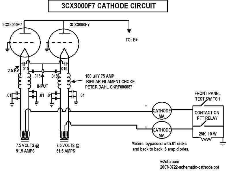
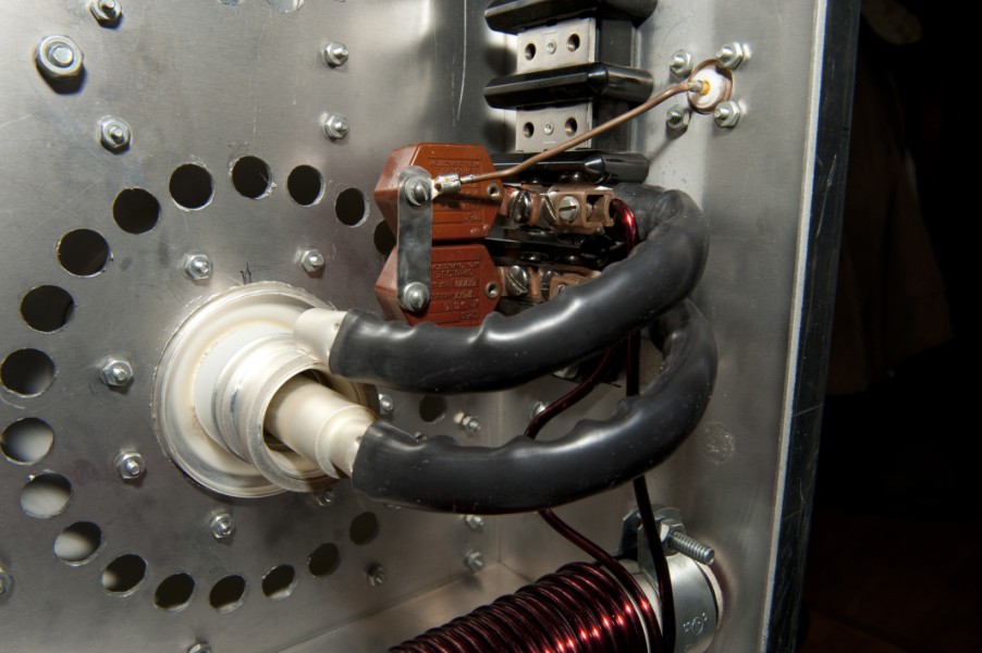
7: Overview of RF input circuit with dual 180 uHy, 76 amp filament chokes and .015
coupling capacitors.
8: Shown is the relay that grounds the tube cathodes and the 12 VDC power supply.
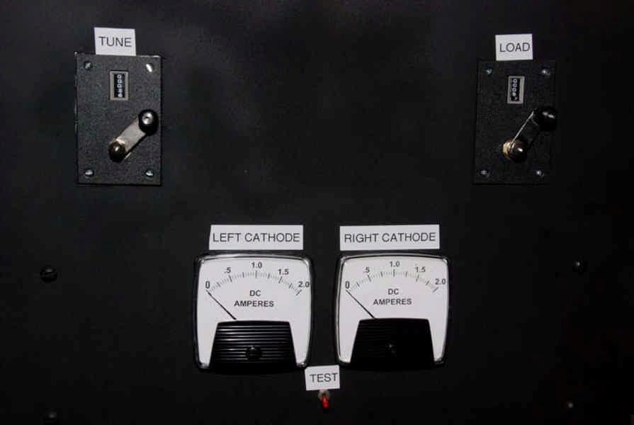
9: Homebrew cathode ammeter shunt (red coil) and front panel test switch.
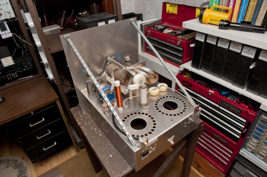
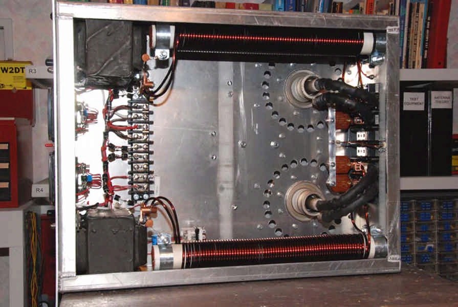
10: Size of chassis: 22" x 17" x 6". Overview of cathode wiring showing
the two Peter Dahl
180 uHy 75 amp filament chokes.
Choke Construction: 16 inches long, 38 bifilar
turns (by count 76 wire turns divided by 2) of #8
wire wound around 7 ferrite rods on
a 1 1/2 inch diameter form. (Not sure how many rods sets
needed for a length of
16 inches).
The choke weighs 6.5 pounds.


11 12
13
14
15
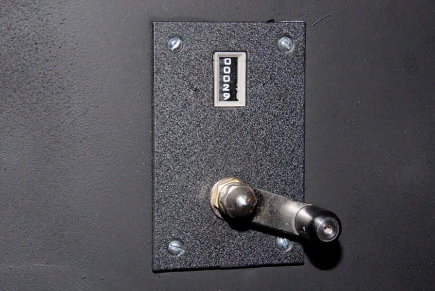
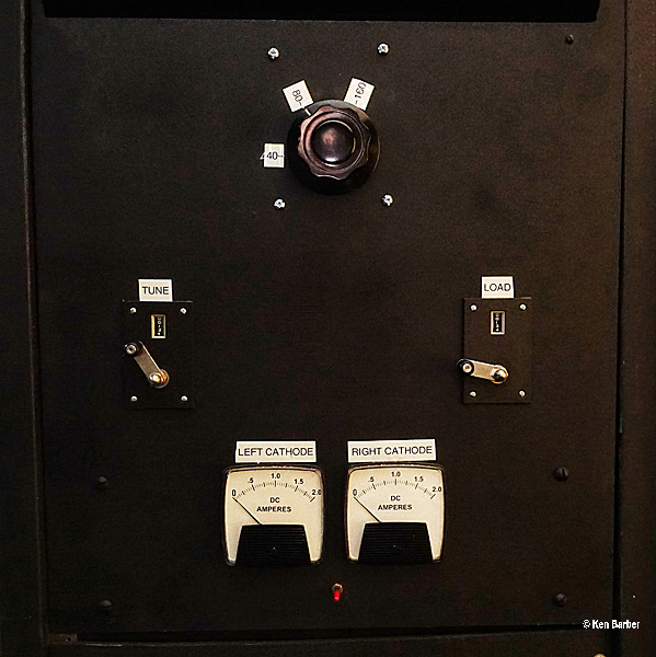
11: Front panel turns counter. (From the Palstar Company in Piqua, Ohio).
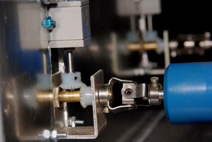
12: Turns counter to vacuum variable coupling.
13: Mounting bracket for vacuum variables (custom made by Bayshore Metal Products Inc,
Keyport, NJ).
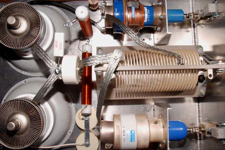
14: 15 KV vacuum variable C1, Jennings UCSL-2750-5N558, measured at 12-540 pf.
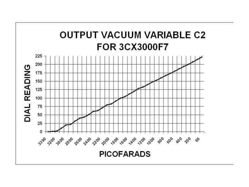
15: 5 KV vacuum variable C2, Jennings CSVF-500-0315, Measured at 50-3300 pf.

16
17
18
19
20
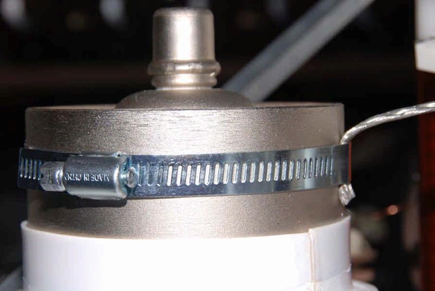
16: Tube connection via standard 4.5 inch dryer clamp and Scotch #25 Electrical
Grounding Braid.
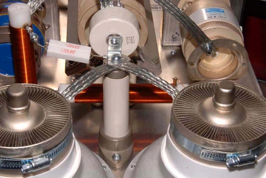
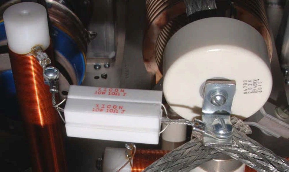
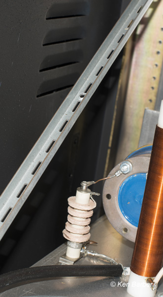
17: Five inch tall standoff insulator with 1/4 inch threads, central support for the plate
connection, the 2020 pf, 40KV, 15 amp plate coupling capacitor and the 10 ohm, 10
watt glitch resistors.
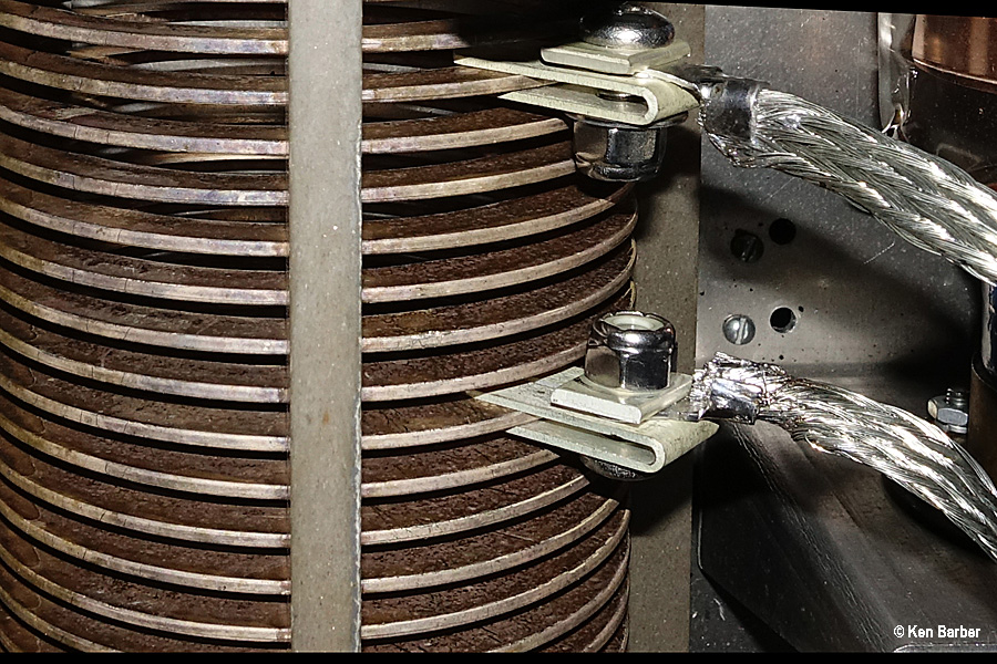
18: Pi-network connections. Gates inductor 3 9/16" dia, 7 1/4" long, 28 turns.
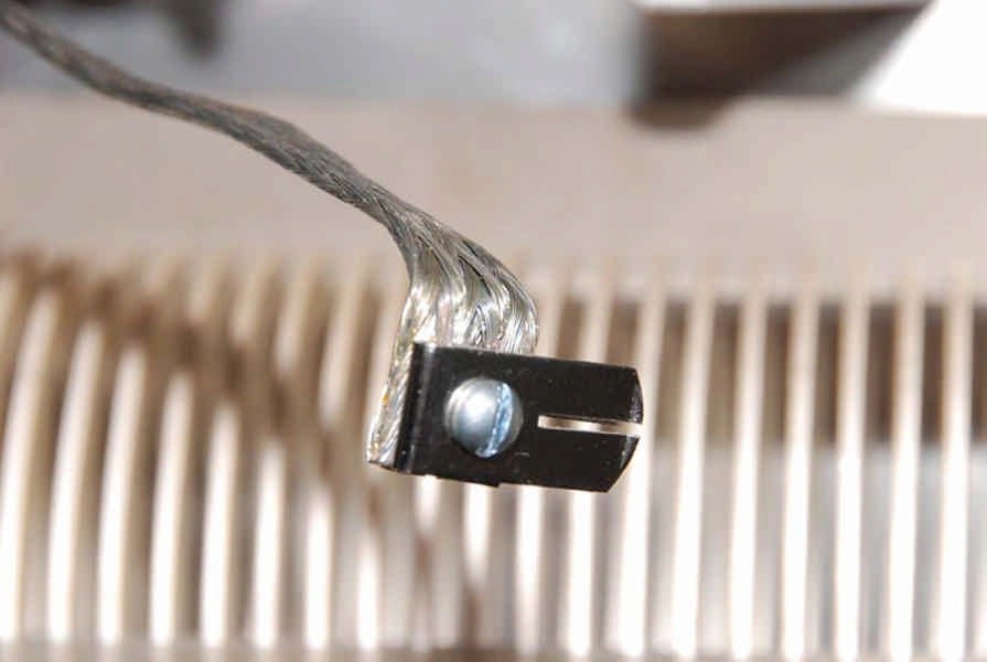
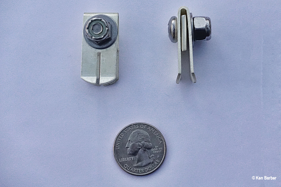
19: Inductor clip, 15 amp (Viking Electronics Technologies, Ltd, Lindenhurst, NY).
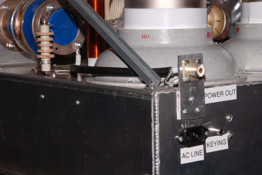
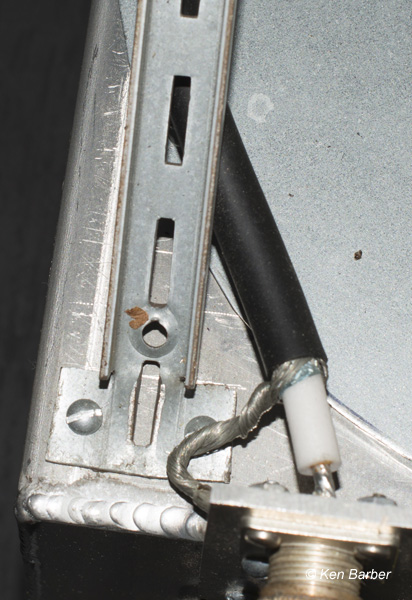
20: Power out coax connector, AC line connector, RCA keying jack and 1 mHy safety
choke.


21
22
23
24
25
21: Millen high voltage connector and ground lug.
22: B+ bypass caps, each 2720 pF, 30KV, 15 amps.
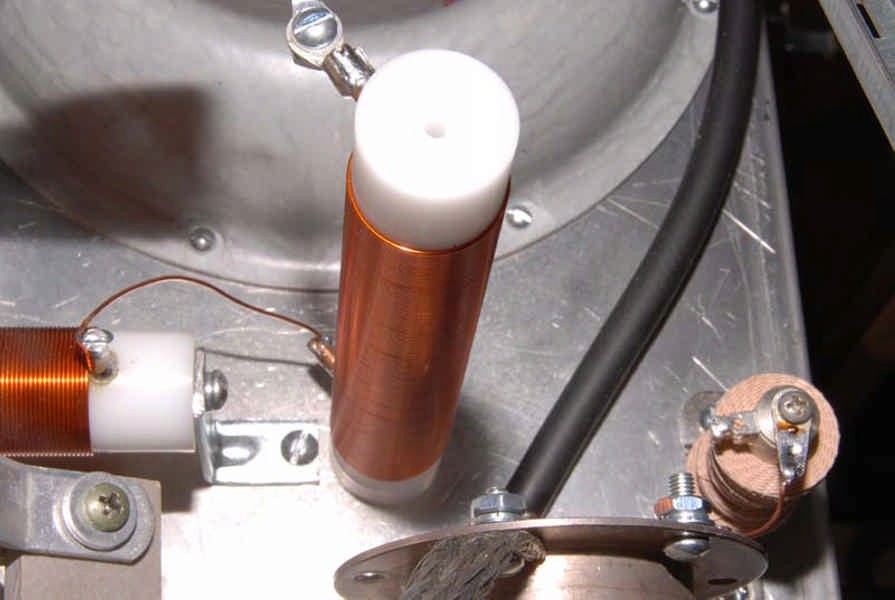
23: Plate choke #1, Peter Dahl 90 uhy, 3 amps.
CONSTRUCTION: 5/8 inch diameter grooved Delrin Rod 6.7 inches long, 123
turns of #24 magnet wire, measuring 5.0 inches long.
24: Plate choke #2, 90 uhy, 3 amps.
25: Glitch resistors, (4) 10 ohm, 10 watt units. I have a minority opinion on glitch resistors.
Most designers plan on having the resistor absorb the hit and discharge the capacitors.
When there is a glitch, I want to know about it immediately. The resistors will explode
and then I vacuum out the remains. When 150 MFD capacitors are charged to
5000
VDC there is serious short circuit current. For fusing, I also have a 4 inch piece of
magnet wire in the B+ line.


26
27
28
29
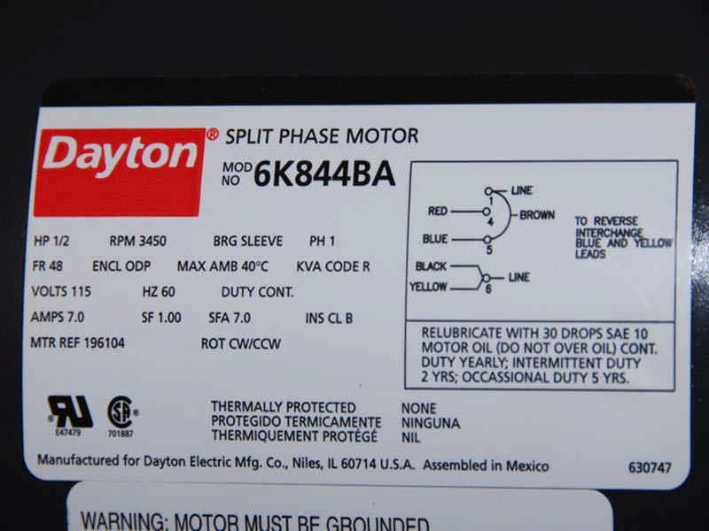
30
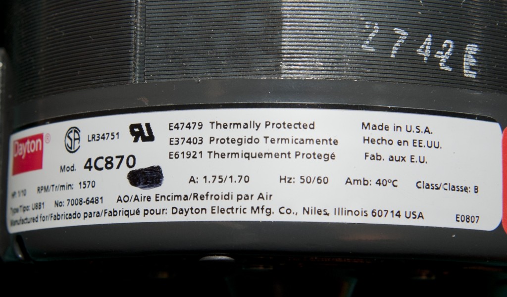
26: Label on 1/2 horsepower, 3450 RPM Dayton split phase motor.
27: Label on 9 inch diameter Dayton blower.
28: 4 inch hole drilled into the 3/4 inch plywood shelf which holds the RF DECK.
29: Dryer hose installed.
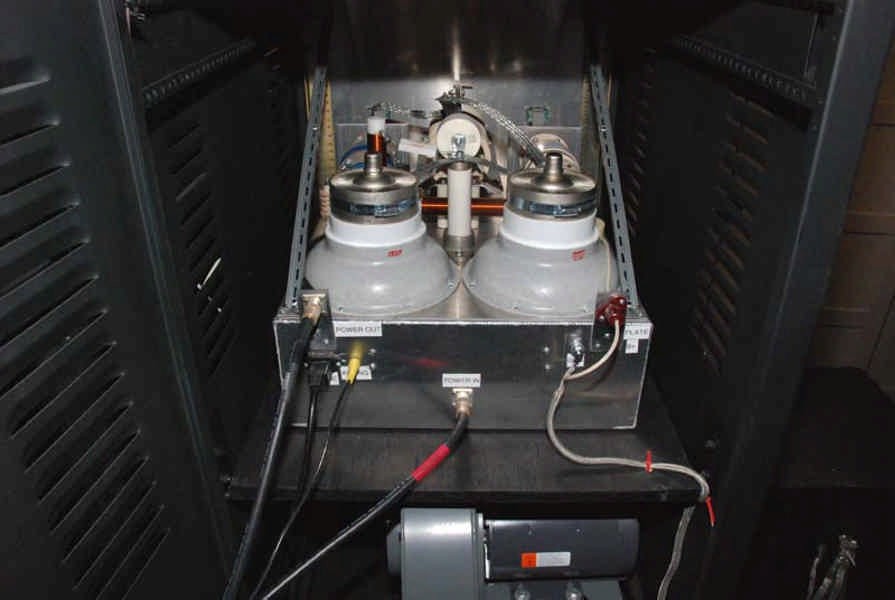
30: Back of RF DECK. More than enough air pressure comes up through the bottom of the
chassis to cool the tubes.
ORIGINAL CHASSIS TO FRONT PANEL HARDWARE:

The chassis was braced to the front panel by shelf standard rods at both rear corners of the chassis. The ends of the shelf standard rods were cut with a hacksaw and banged flat with a hammer. Standard 10-32 hardware was used to fasten the end of the standards to the front panel.

31
32
33
34
31: Schematic of the plate circuit.
32: Schematic of the cathode circuit.
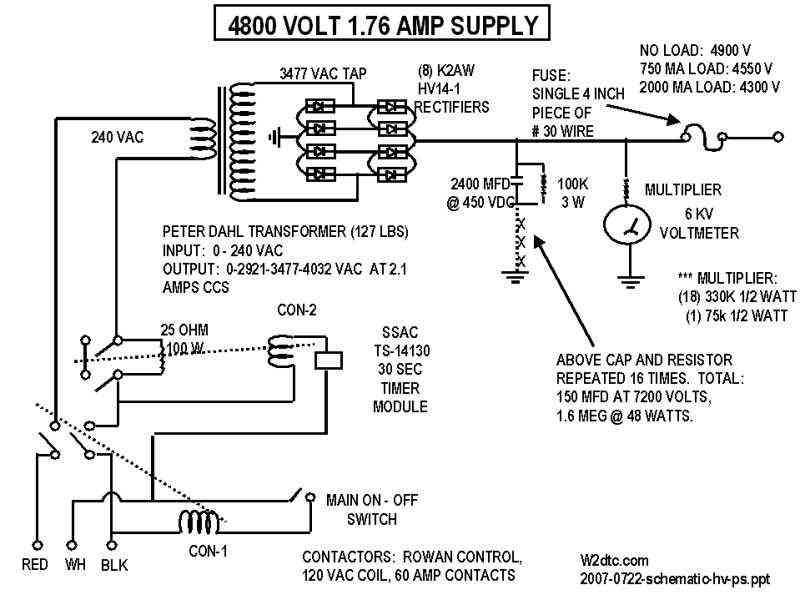
33. Schematic of the high voltage power supply.
Click
HERE to see that power supply.
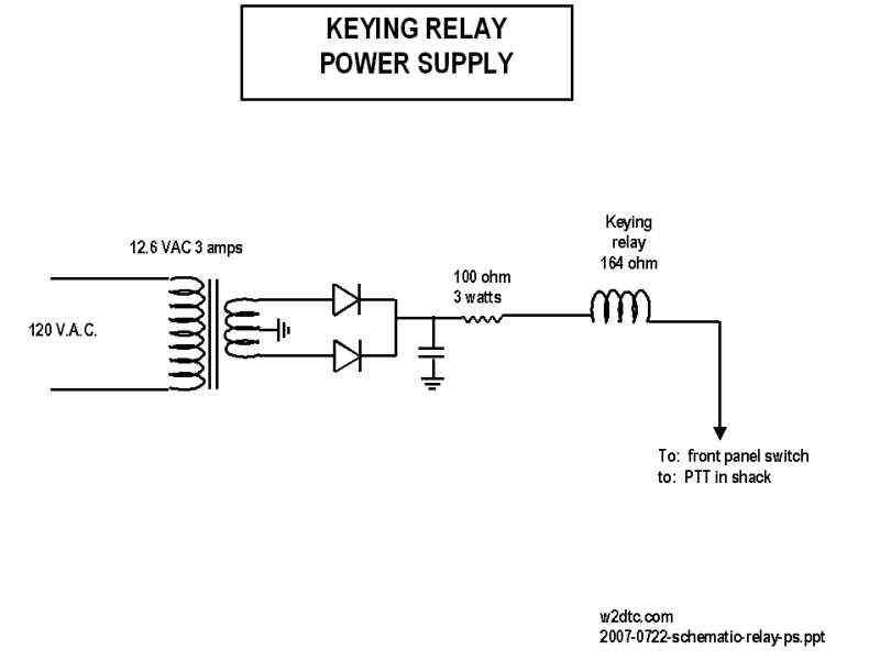
34: Schematic of the keying relay power supply.


35
36
37
38
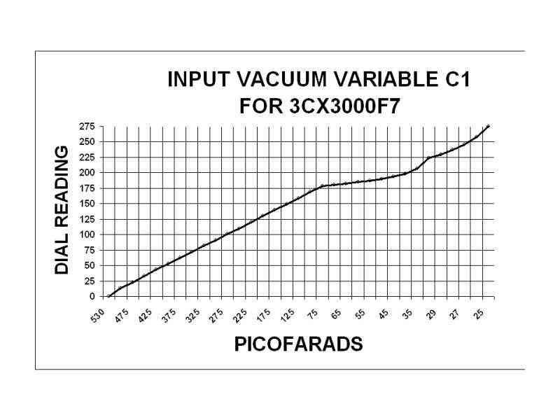
35: Turns counter dial reading vs picofarads for input capacitor C1.
36: Turns counter dial reading vs picofarads for output capacitor C2.
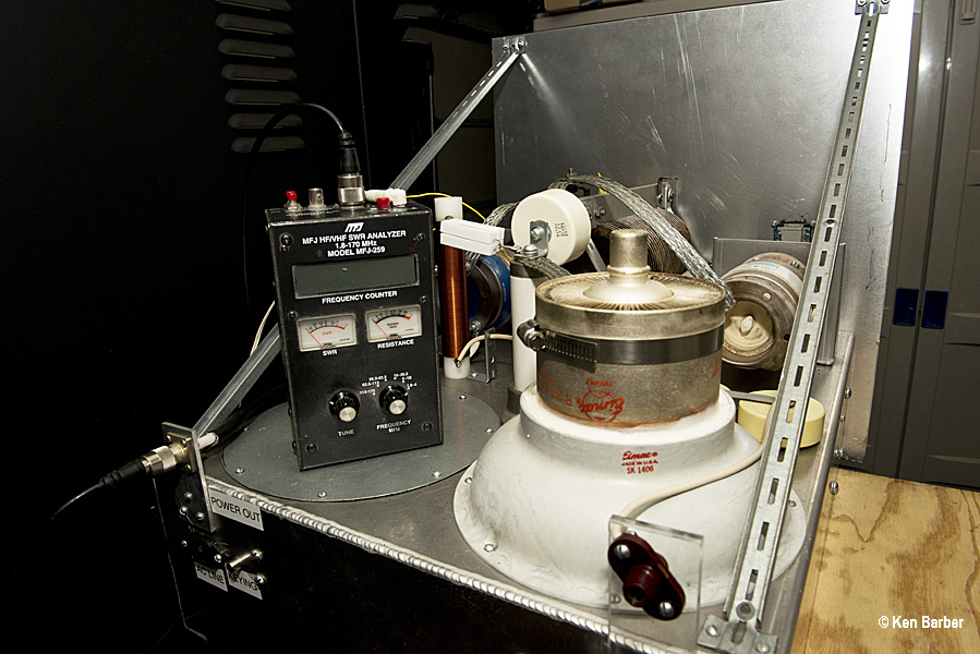
37: Test setup for ballpark pi-network values. With a capacitance checker, I found the
values of the unconnected input and output vacuum variables and set them to the
values of the formulas for a Q of 12. With aligator clips I attached a resistor from plate
to ground equal to the calculated plate resistance. I adjusted the coil taps until I
obtained a low SWR on the MJF-259. This is not perfect test, but it gets the
pi-network into the ballpark. (All power is off for this test).
38: Block diagram of test setup.
1. The initial tests were made in class AB2. In AB2, this amplifier will put out twice the
output of the single 3CX3000F7 and requires twice the drive.
2. Bias diodes are unnecessay with the 3CX3000F7 in a cathode driven grounded grid
configuration. With the grids grounded directly to the chassis, the center tap of the
filament transformer can be switched directly to the chassis to activate the amplifier.
3. Under full load, there is no significant difference in output between the amp running at
4900 volts on the plate or 4300 volts. With the higher plate voltage, the idling current
is higher and slightly less drive is required for the same output power.
4. Tuning for maximum power the amp produces 20 times the input power with fairly good
efficiency; however when adjusted with a signal generator and a scope, the output
power is only 12 times the input
power. It is clear that an
oscilloscope is an absolute essential when using linear amplifiers.
The big amp ran flawlessly for 6 years until it had it's first problem (found a shorted .015 transmitting mica cap in one of the cathodes). As an old guy, I realized that I could no longer lift the RF Deck out of the rack without help. I decided that the extra 3DB power difference (1/2 an S unit) was not worth the extra physical weight so I removed one of the tubes. The plan also included replacing the very high noise level cooling system.
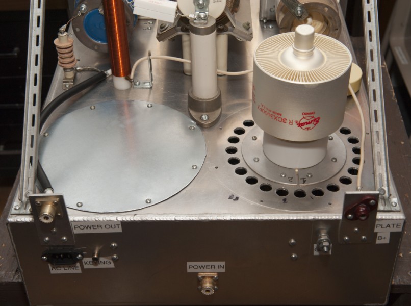
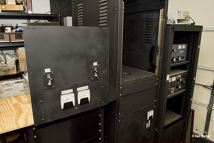
THE ORIGINAL 'TWO HOLER':
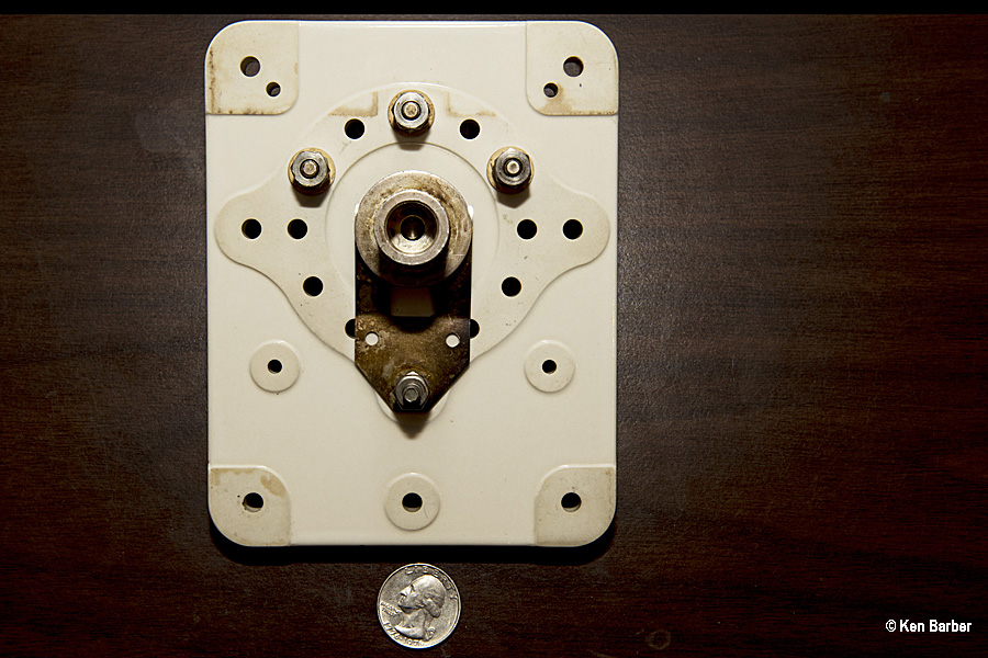
THE STRIPPED DOWN CHASSES AND SPARE PARTS.
COVERED THE MISSING TUBE HOLE.


Using the chimney as a template, I cut a thin piece of aluminum stock and lined
the edge with rubber tape as an air tight gasket.
INSTALLED A NEW EIMAC 3CX3000F7.
A few years ago I started seriously collecting amp parts. As I was
working on this project, I had this nagging feeling that perhaps I had purchased a new
tube sometime back. Sure enough, I found the shipping box for the new tube. While I usually use Econco rebuilts, this ebay purchase
of a brand new Eimac tube was at a very
reasonable price.
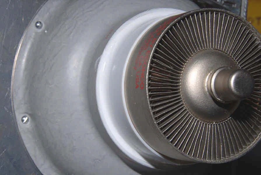
SEALED THE OVERSIZED CHIMNEY.

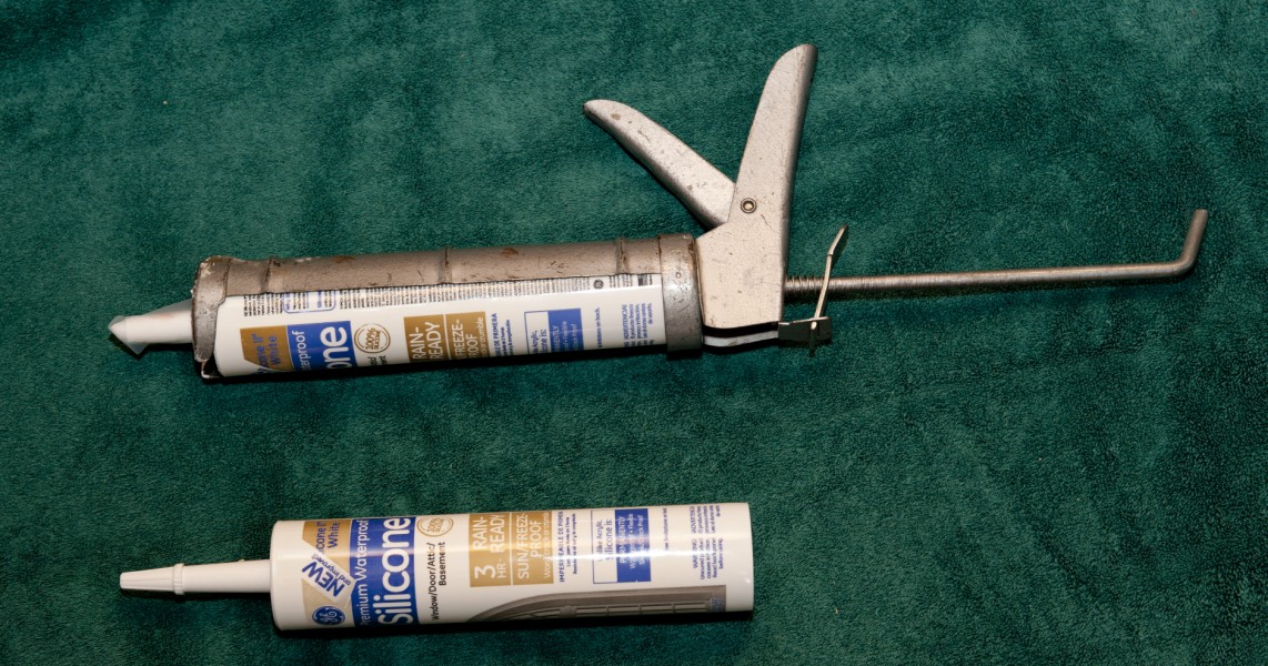
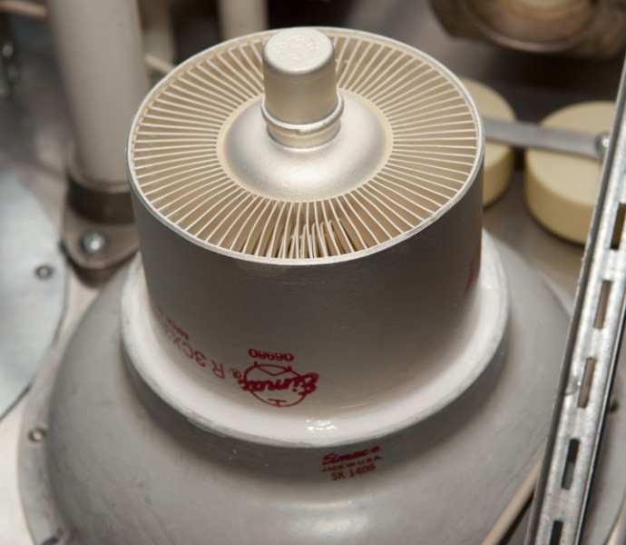

In the original configuration I chose the
oversized SK1406 chimneys. As you can see in the first photo, there is a
gap between the tube and the chimney. I filled the gap with GE Silicone
II, which has an operating temperature of up to 400 degrees Fahrenheit.
COMPLETED THE PLATE CIRCUIT WITH THE BRAIDED STRAP AND CLAMP.
COMPLETED THE CATHODE CIRCUIT WITH REINSTALLATION OF MICA CAPS.
CHANGED PI-NET INDUCTANCE TAP.
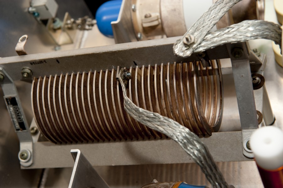
Removing one of the tubes and running less plate
current raised the plate resistance, requiring two more turns on the pi-net
coil to maintain a calculated Q of 12.
REPLACED THE COOLING SYSTEM WITH THIS ONE.

The original blower was a 1/2 HP very loud system. I replaced it with a much quieter 495 CMF fan.


Plate circuit
Cathode circuit
1. The amplifier came online with no problems. It puts out 1/2 the power of the two holer.
2. The cooling blower is much quieter than the original.
3. The additional turns on the pi-net inductor worked fine.
4. I'm able to install the RF deck without the need of a helper.
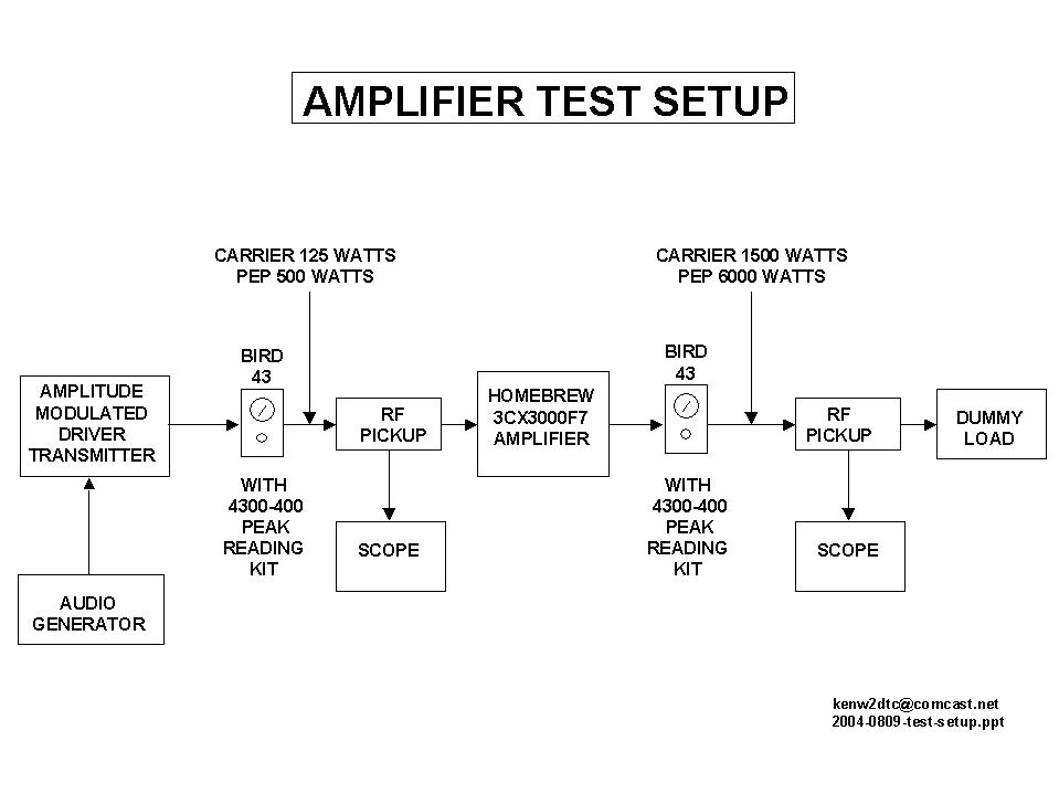 Block diagram of test setup prints
best in landscape orientation.
Block diagram of test setup prints
best in landscape orientation.
NOTE: When the final tank circuit was tuned for the highest RF carrier, using Bird wattmeter
readings, significantly more output power was obtained than the data shown
below; however, when modulation was applied, the oscilloscope showed distortion.
The final tank circuit was retuned for true linearity with an AM waveform on the scope
and the data (shown below) was recorded. The plate voltage
was 4500 VDC.
Input and output power in linear operation:
25 watts in---- 300 watts out
50 watts in-----600
watts out
100 watts in---1200 watts out
200 watts in---2400 watts out
300 watts in---3600 watts out
400 watts in---4800 watts out
500 watts in---6000 watts out
Since the output power is twelve times the input power, I set the AM driver transmitter for
31.25 watts of carrier (125 watts PEP) which yields a 375 watt carrier and a clean 1500 watts PEP. Another nice thing about the extra 3CX3000F7 tube plate dissipation is that
I don't have to retune the amp to move around the band, even when the antenna
feed presents a less than desired SWR reading.
2015, It's the 10th year anniversary for this amp and I decided to add a band switch and make it a tri-band amp.
Removed the amp from the operating rack. Using the information on this webpage titled: DATA AND SETUP FOR RUNNING TESTS, I set up the pi-net C1 and C2 for each band using the MFJ-259. I used the plate resistance value from the 3CX3000F7 tube specs for a cathode driven linear amp. Then I attached a carbon resistor equal to the plate resistance from plate to ground. I was delighted that my MFJ tests were quite accurate ! I didn't have to change any taps on the inductor during testing.
160 all turns but the last 2 from the hot end
80 12 turns from cold end
40 5 turns from cold end.
This very heavy duty switch was purchased at a hamfest years ago. It probably came from a high power military antenna tuner.


20 Amp silver plated Inductor Clips from Kintronic Laboratories.
PI NETWORK TURNS COUNTER READINGS FOR MY CURRENT ANTENNAS:
FREQ C1 C2
1885 48 173
3885 124 134
7180 151 151