![]()
In September 2010, the vintage, vacuum tube Amateur Radio Station shown on this webpage was replaced with software defined radio equipment. Click HERE to see the new Flex Radio Station Equipment.
1
2
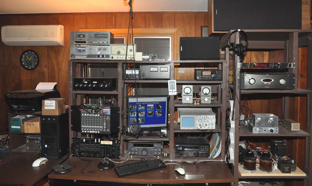
1: Transceivers, audio chain and receivers inside the shack.
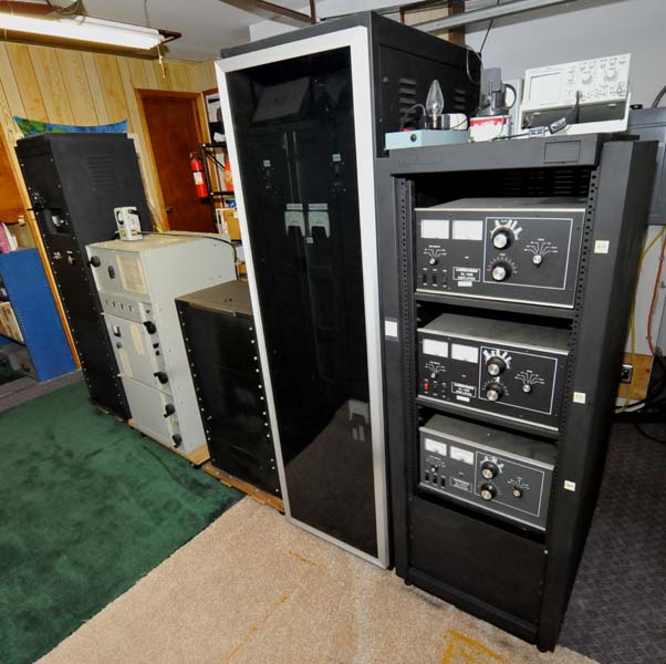
2: Linear amplifiers in the garage.
1
2
3
4
5
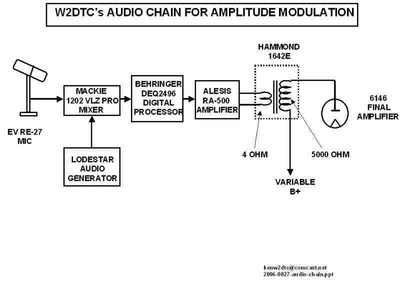
1: Audio chain overview.
2: Electro-Voice RE27N/D dynamic microphone, 150 ohm balanced output, 45 Hz to 20 kHz response.
The Electro-voice model 309A uses shock mount elastic bands (part number 78297)
and the bands last about 2 years.
Click
HERE to see my homebrew, no vibration mike "boom".
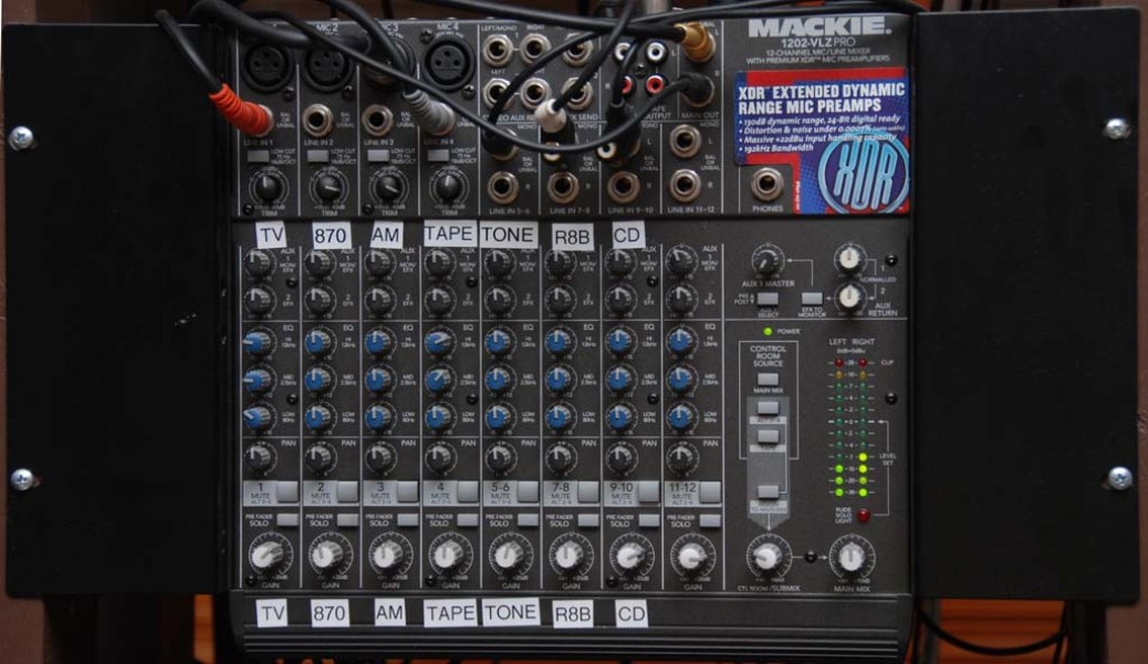
3: Mackie 1202-VLZ 12 channel mic/line Pro Mixer. Bullet-proof design for RF rejection. Very low noise and enough gain for low impedance microphones. Because of my Behringer DEQ2496, my Mackie mixer settings are all flat. Prior to the Behringer, the Mackie EQ did an excellent job on its own; however it did not offer special frequency tweaking and compression that the Behringer provides.
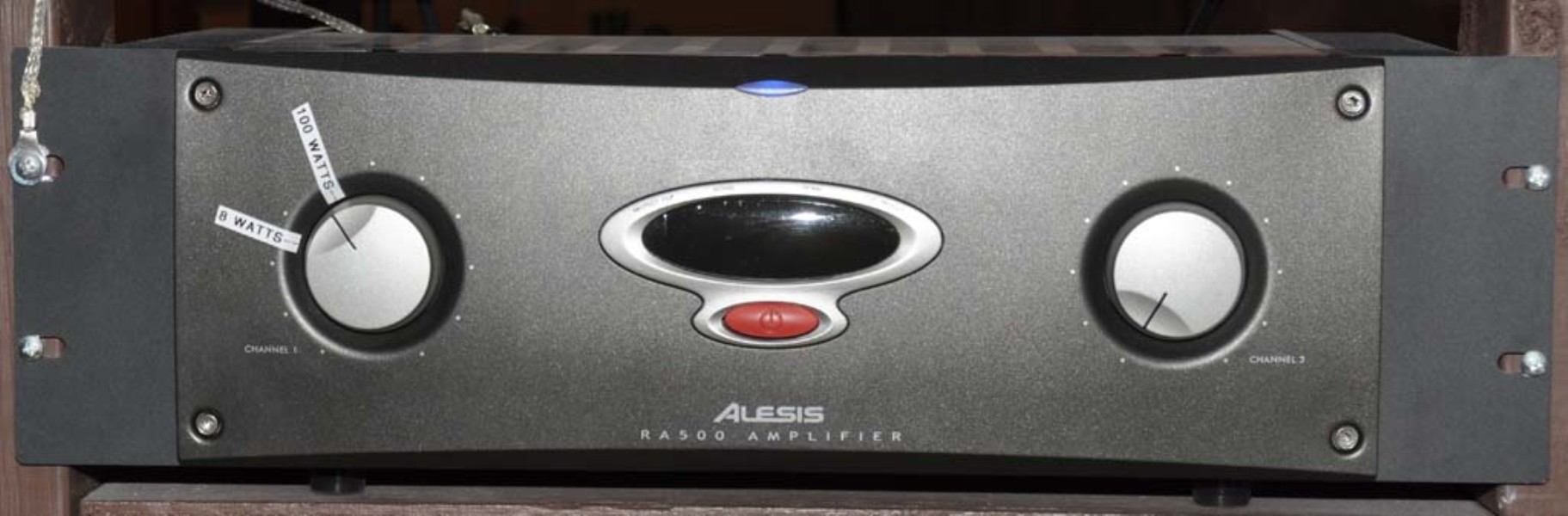
4: Alesis RA500 250 watts per channel power amplifier (10 Hz to 70 kHz).
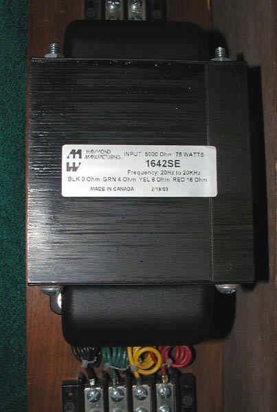
5: Hammond 1642SE single ended audio transformer, 20 Hz to 20 kHz, 75 watts, 300 ma, 5000 ohms to 4/8/16 ohms.
6
7
8
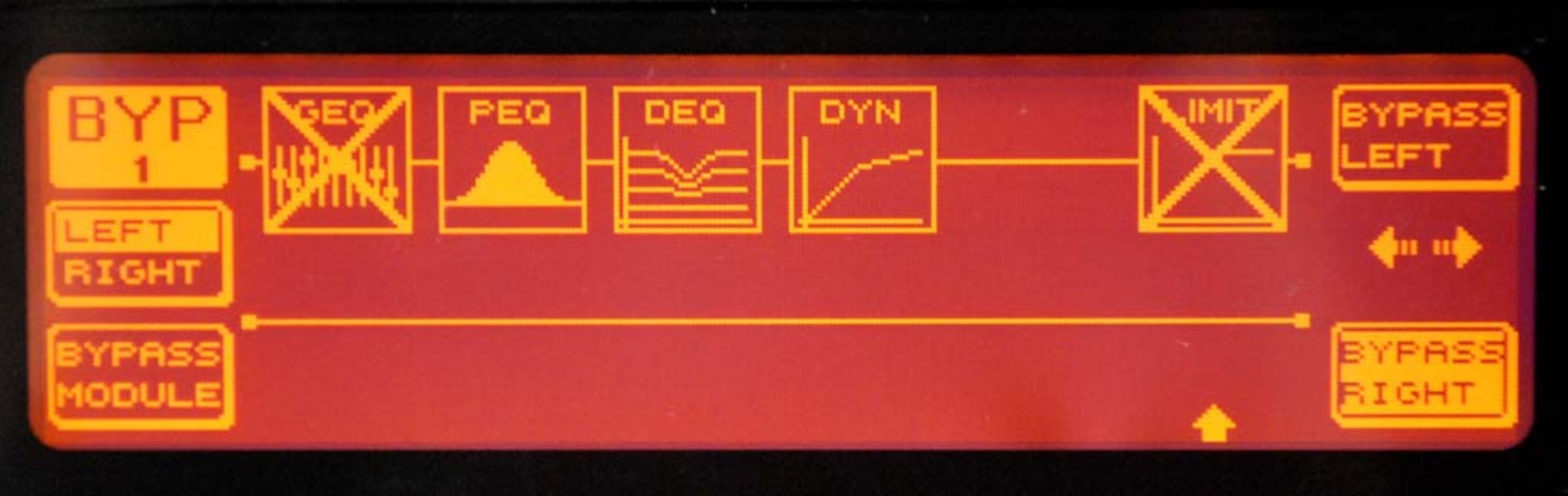
6: Behringer DEQ2496 digital audio processor BYPASS DISPLAY. For initial settings I turned off the GEQ and LIMIT functions. The DEQ and DYN functions were set with initial parameters from Tyler KA0KA, which are posted on the NU9N.COM internet site.
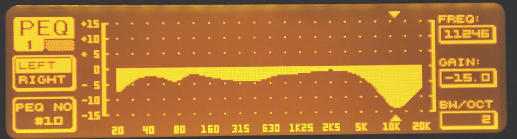
7: Behringer DEQ2496 digital audio processor PEQ DISPLAY. Using an audio
signal generator, I tweaked the EQ menu until my scope, which was monitoring the
RF output of my homebrew transmitter, showed a flat response from 0 to 5 kHz. While my
homebrew transmitter was fairly flat from 20 Hz to 5 kHz, the initial
Tyler KA0KA DEQ, DYN parameters influenced the final settings. (Above 5
kHz, I attenuated the audio dramatically to reduce bandwidth).
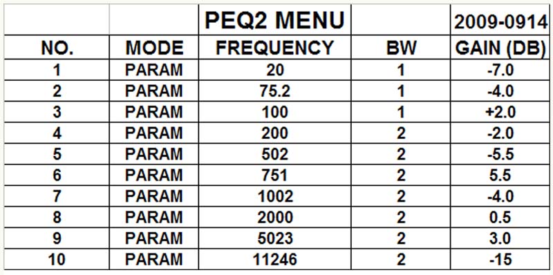
8: My Parametric EQ Settings.

1
2
3
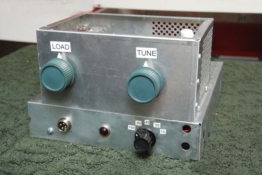
1: The homebrew 6146 amplitude modulated class "C" driver transmitter. PI-net parts from a disgarded DX-60 and plate modulated by an external power supply and modulator (see audio chain overview above), variable power (0-50 watts) and flat audio response from 20 Hz to 6 kHz.
1
2
3
4
5
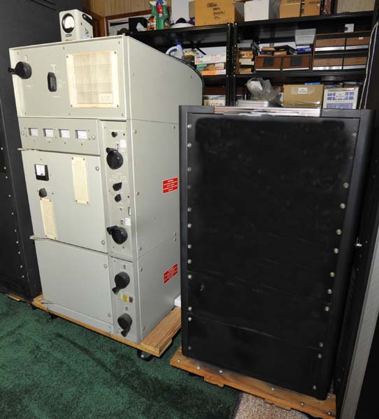
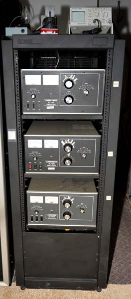
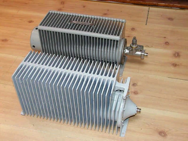
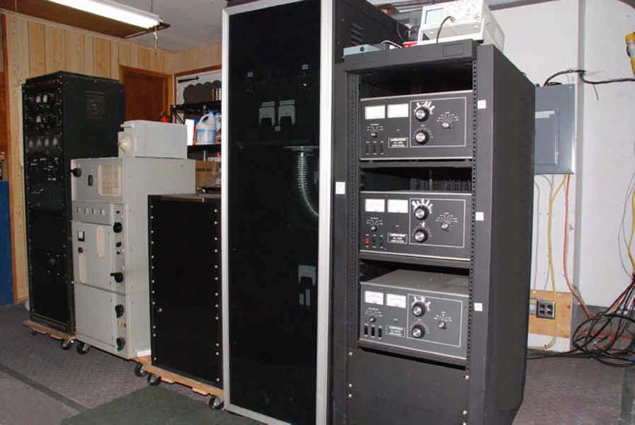
1. Overview of the linear amplifiers in the garage. They were moved out of the shack to
eliminate blower noise and heat.
2: Homebrew conversion of a Plasma Amp to a 40 meter linear with a
3CX3000F7.
Click
HERE
to see this amplifier.
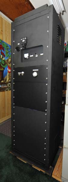
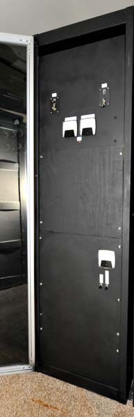
3. Homebrew 3CX3000F7, 160 thru 20 meter linear built inside a Gates
cabinet and the
accompanying homebrew high voltage supply in the black Bud cabinet.
Click
RADIO RECEIVERS:
1
2
3
4
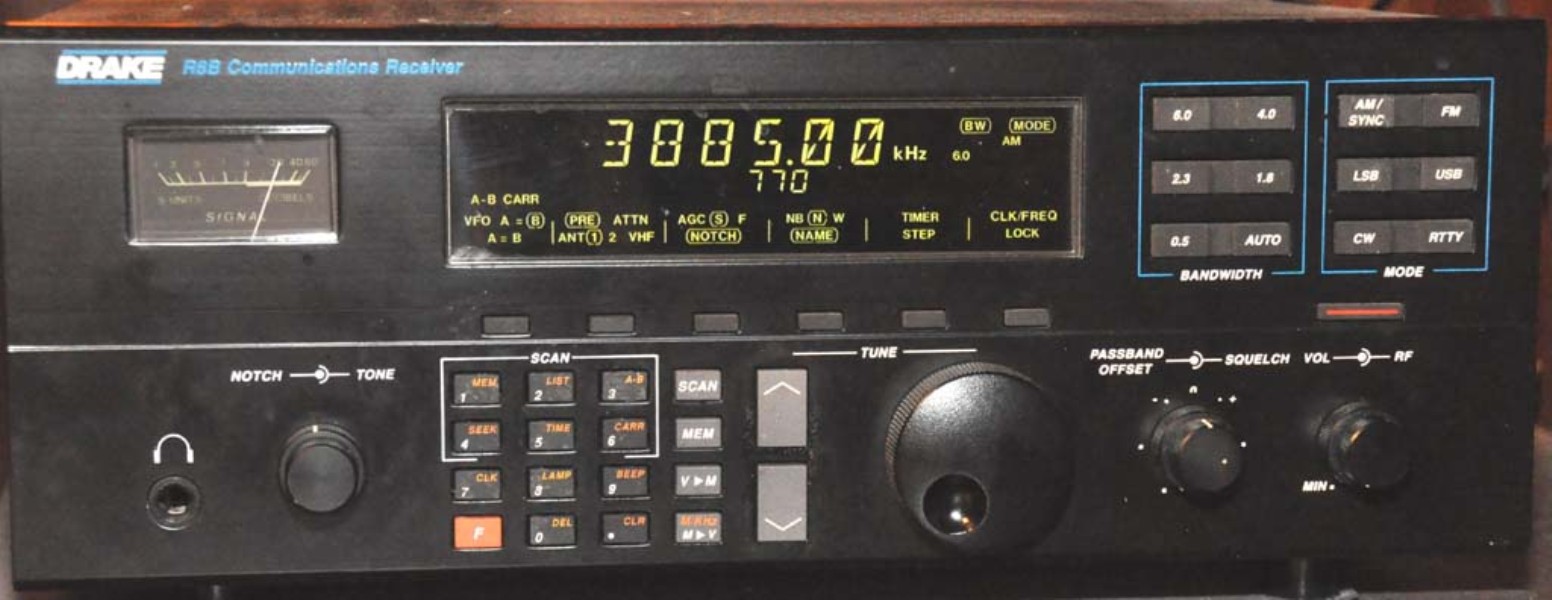
1: Drake R8B tuning from 10 kHz to 30,000 kHz for LSB, USB, RTTY, CW, AM and FM. One of the really nice features of the Drake is that if there is an interfering carrier above or below the AM station you are listening to, you can put the receiver in "sync detect" and select either upper or lower sideband and the interfering carrier is eliminated.
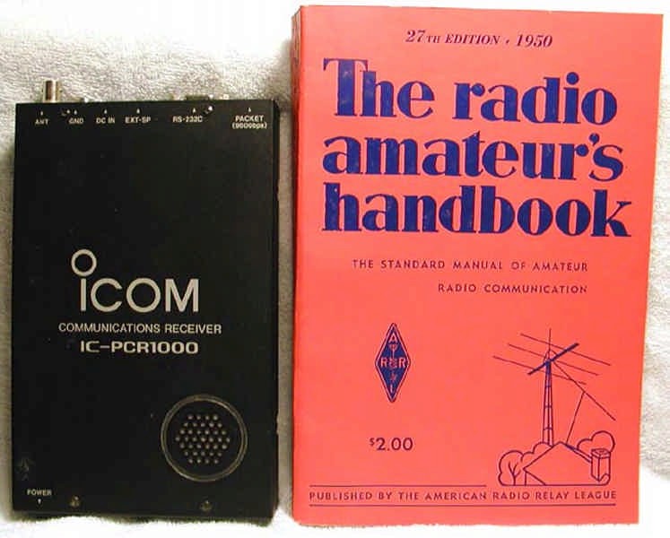
2. The ICOM IC-PCR1000 computer controlled receiver. 10kHz to 1300 mHz, AM, FM, CW, WFM, SSB).
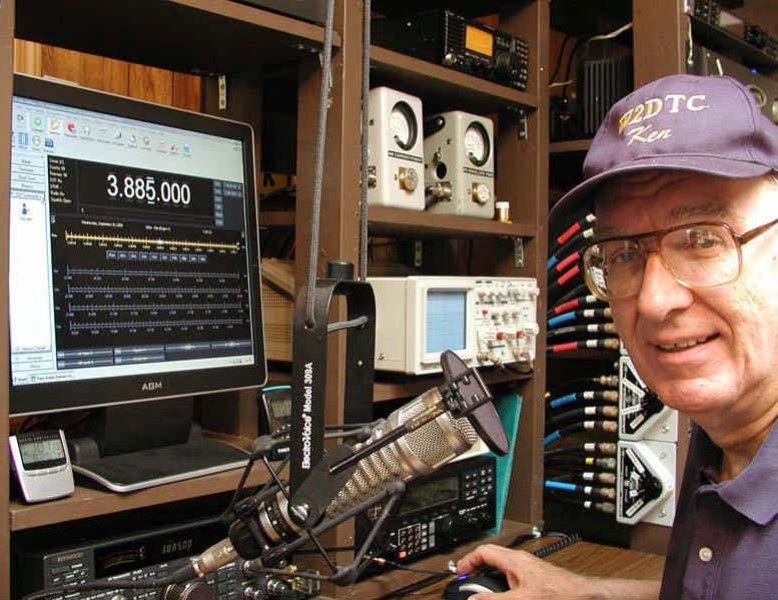
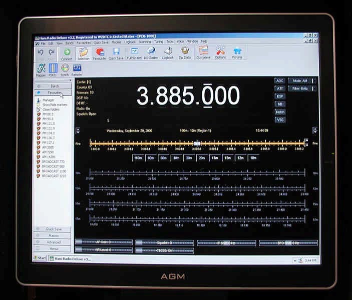
3. Computer screen showing Ham Radio Deluxe software controlling the PCR-1000.
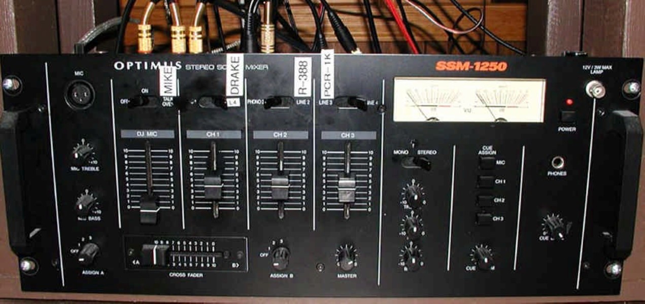
4: Optimus mixer to enhance audio and match output levels from the Drake R8B and the PCR-1000 recievers to a HI-FI amplifier and speaker.
1
2
3
4
5
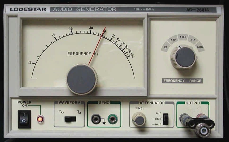
1: Lodestar AG-2601A, Audio signal generator. Provides both sine wave and square wave output from 10 HZ thru 1 MHZ. This generator is plugged into the station audio mixer and is used for tuning up the linear amplifiers in AM service. It is also used to "sweep" the AM driver transmitter to find out its "HI-FI" capability.
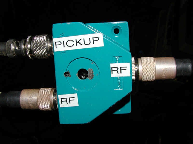
2: Homebrew RF sampler made from an A-B coax switch: The A-B switch is removed, the "A" strap carries the RF from transmitter to antenna and the "B" strap, in parallel, grounded at one end, is the RF pickup and feeds my oscilloscope. Off-the-air RF envelope examination is a must for operation of Linear Amplifiers in AM service.
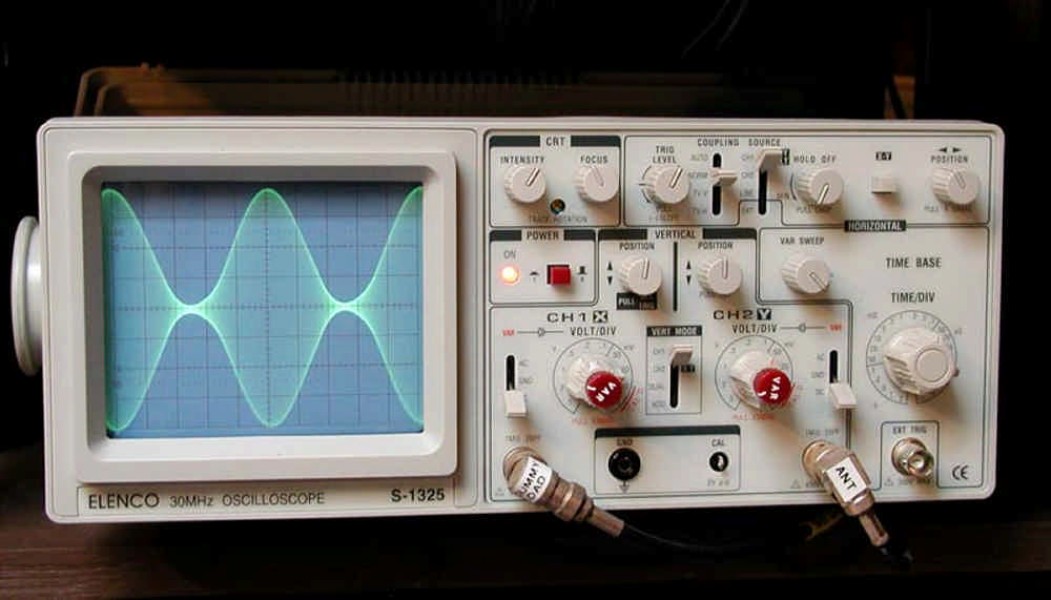
3: Elenco S-1325, dual trace, 30 Mhz Oscilloscope. This scope is invaluable for tuning up the linear amplifiers in Amplitude Modulation service.
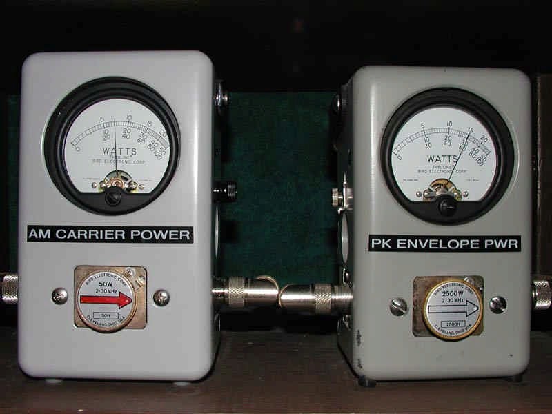
4: The Bird 43 wattmeter (left) is measuring AM carrier input power to the AL-1500 linear amplifier and the Bird 43 meter (right, with 4300-400 peak reading kit) is reading the peak envelope power output of the AL-1500. (Note: I replaced the batteries with two 9 volt power modules ("wall warts") and I now leave the PEP kit on all the time).
5: The dummy load (background) with the external RF sampler is the Bird Termaline RF Load-Coupler, model 6411 rated at 500 watts at 50 ohms. The Bird dummy load plus RF sampler weights 23.5 pounds. The dummy load (foreground), is a US Navy DA-75/U, rated at 1000 Watts average at 51.5 ohms nominal in the range of 1.3 to over 1000 mHz. The DA-75/U while looking similar in size to the Bird 6411 is actually 3 inches longer, has much thicker radiators and it weights 33 pounds (10 pounds more than the 500 watt Bird 6411).
1
2
3
4
5
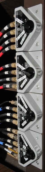
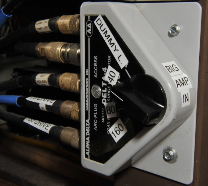
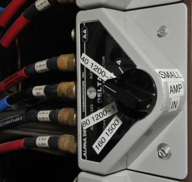
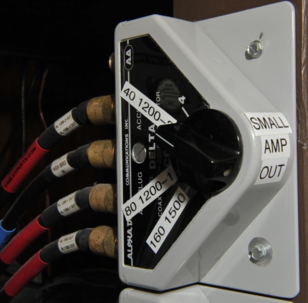
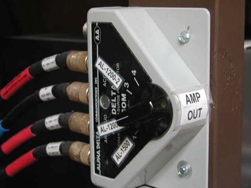
1: Alpha Delta antenna coax switches to amplifiers, antennas and dummy load. All antennas are fed with LMR 400 coax.
2: Antenna selection switch (160 METERS: Coax fed dipole with center at 60 feet and ends somewhat lower. 40 METERS: inverted V, sharing the same coax as the 160 meter dipole. 75 METERS: Coax fed dipole with center at 60 feet).
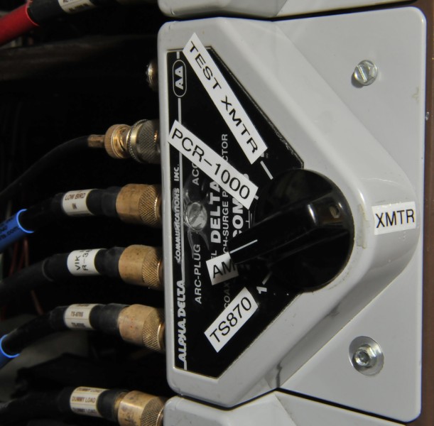
3: Transmitter/transceiver selection switch.
4: Linear Input Switch.
5: Linear Output Switch.
1
2
3
4
Measurements by an MFJ-259B at the shack end of the coax:
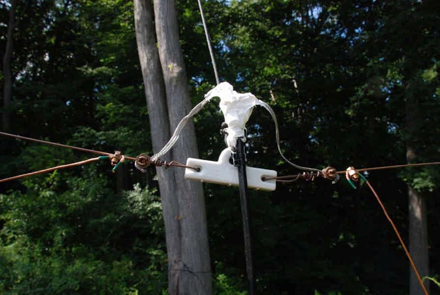
1: 75 meter dipole: 124 feet long of #10 copperweld, fed at the center with LMR 600 Coax, 60 feet high running north-east to south-west.
2: 160 meter dipole: 225 feet long of #10 copperweld, fed at the center with LMR 400 Coax, 60 feet high at one end, 15 feet at the other end running north-east to south-west.
3: 40 meter inverted V: 67 feet long of #12 flexwire, fed at the center with the same LMR 400 Coax that feeds the 160 meter dipole, 60 feet high running north-east to south-west. I found that the length was critical. I had to chop and test, chop and test to get it to the desired range.
4: Common feed point for 160 meter dipole and 40 meter inverted V. SO-238 is covered with GE-silicon rubber. The LMR 400 is fastened to the center insulator with two UV tie raps.
For the folks that landed on this webpage, similar to those who emailed me, hoping to start a "small station in South Africa" or "a religious station in Zimbabwe" or "a community radio station" etc, please read the following links before investing a penny in equipment:
Mulcher FM
The Federal Communications Commission
IBS Intercollegiate Broadcasting System
Costs of starting a radio station
![]()